Mitsubishi Outlander GS45X. Manual - part 675


  Index      Mitsubishi     Mitsubishi Outlander GS45X - service repair manual


Search            


Content   ..  673  674  675  676   ..


Mitsubishi Outlander GS45X. Manual - part 675


MULTIPORT FUEL INJECTION (MFI) DIAGNOSIS

TSB Revision

MULTIPORT FUEL INJECTION (MFI) <2.4L ENGINE>

13A-523

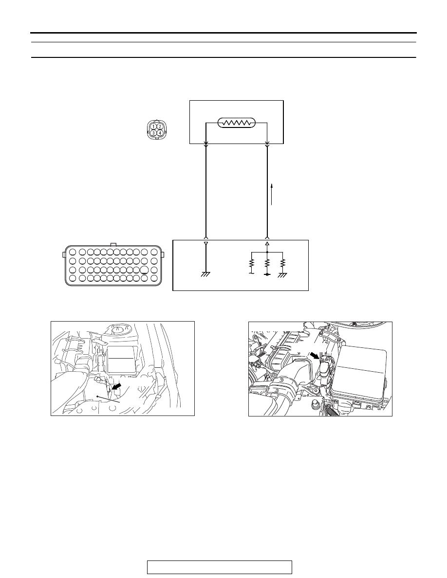
DTC P0515: Battery Temperature Sensor Circuit

.

CIRCUIT OPERATION

• Approximately 5 volts are applied to the battery 

temperature sensor output terminal (terminal No. 
2) from the ECM (terminal No. 98) via the resistor 
in the ECM. The ground terminal (terminal No. 3) 
is grounded with ECM (terminal No. 101).

• The battery temperature sensor is a negative 

temperature coefficient type of resistor. When the 
battery temperature rises, the resistance 
decreases.

• The battery temperature sensor output voltage 

increases when the resistance increases and 
decreases when the resistance decreases.

.

TECHNICAL DESCRIPTION

• The battery temperature sensor converts the bat-

tery temperature to a voltage.

• The ECM checks whether this voltage is within a 

specified range.

.

DESCRIPTIONS OF MONITOR METHODS

Battery temperature sensor output voltage is out of 
specified range.

.

AKA00474

71 72 73 74 75 76 77 78 79 80 81 82

83 84 85 86 87 88 89 90 91 92 93 94

95 96 97 98 99

100 101 102 103 104

112 113 114

109

108

107

110 111

115 116

106

105

118

117

101

98

BATTERY TEMPERATURE
SENSOR (INTEGRATED IN
BATTERY CURRENT SENSOR)

3

2

5 V

BATTERY TEMPERATURE SENSOR CIRCUIT

A-65

B-11

ENGINE
CONTROL
MODULE

GRA

Y

BLUE-BLA

CK

AC

AK900202 AF

A-65 (GR)

Connector: A-65

Battery

AK704097AB

Connector: B-11

B-11 (GR)

MULTIPORT FUEL INJECTION (MFI) DIAGNOSIS

TSB Revision

MULTIPORT FUEL INJECTION (MFI) <2.4L ENGINE>

13A-524

DTC SET CONDITIONS

Check Condition

• 2 seconds later after the ignition switch has been 

in ON position or just after the engine has started 
up.

Judgement Criterion

• Battery temperature sensor output voltage is 

more than 4.6 V (corresponding to a battery tem-
perature of 

−50°C or less) for 2 seconds.

or

• Battery temperature sensor output voltage is less 

than 0.2 V (corresponding to a battery tempera-
ture of 90

°C or more) for 2 seconds.

.

TROUBLESHOOTING HINTS (The most 
likely causes for this code to be set are: )

• Battery temperature sensor failed.

• Open/shorted battery temperature sensor circuit, 

harness damage or connector damage.

• ECM failed.

DIAGNOSIS

Required Special Tools:

• MB991958: Scan Tool (M.U.T.-III Sub Assembly)

• MB991824: V.C.I.

• MB991827: USB Cable

• MB991910: Main Harness A

• MB992110: Power Plant ECU Check Harness

STEP 1. Check harness connector A-65 at battery 
temperature sensor for damage.
Q: Is the harness connector in good condition?

YES : Go to Step 2.
NO :  Repair or replace it. Refer to GROUP 00E, Harness 

Connector Inspection 

P.00E-2

. Then go to Step 12.

STEP 2. Check the battery temperature sensor.

• Check battery temperature sensor itself (Refer to GROUP 

54A 

− Battery − Inspection − Battery Current Sensor Check 

P.54A-12

)

Q: Is the check result normal?

YES : Go to Step 3.
NO :  Replace the battery current sensor. Then go to Step 

12.

STEP 3. Measure the sensor supply voltage at battery 
temperature sensor harness side connector A-65.
(1) Disconnect the connector A-65 and measure at the harness 

side.

(2) Turn the ignition switch to the "ON" position.
(3) Measure the voltage between terminal No. 2 and ground.

• Voltage should be between 4.5 and 4.9 volts.

(4) Turn the ignition switch to the "LOCK" (OFF) position.
Q: Is the measured voltage between 4.5 and 4.9 volts?

YES : Go to Step 7.
NO :  Go to Step 4.

AKA00476

1

3

2

4

AC

A-65 harness 
connector: 
component side

MULTIPORT FUEL INJECTION (MFI) DIAGNOSIS

TSB Revision

MULTIPORT FUEL INJECTION (MFI) <2.4L ENGINE>

13A-525

STEP 4. Check harness connector B-11 at ECM for 
damage.
Q: Is the harness connector in good condition?

YES : Go to Step 5.
NO :  Repair or replace it. Refer to GROUP 00E, Harness 

Connector Inspection 

P.00E-2

. Then go to Step 12. 

STEP 5. Check for open circuit and short circuit to ground 
between battery temperature sensor connector A-65 
(terminal No. 2) and ECM connector B-11 (terminal No. 98).
Q: Is the harness wire in good condition?

YES : Go to Step 6.
NO :  Repair it. Then go to Step 12.

STEP 6. Using scan tool MB991958, read the diagnostic 
trouble code (DTC).

CAUTION

To prevent damage to scan tool MB991958, always turn the 
ignition switch to the "LOCK" (OFF) position before con-
necting or disconnecting scan tool MB991958.
(1) Connect scan tool MB991958 to the data link connector.
(2) Start the engine and run at idle.
(3) After the DTC has been deleted, read the DTC again.
(4) Turn the ignition switch to the "LOCK" (OFF) position.
Q: Is DTC P0515 set?

YES : Replace the ECM. When the ECM is replaced, 

register the ID code. Refer to GROUP 42B, Diagnosis 
− ID Code Registration Judgment Table <Vehicles 

with KOS> 

P.42B-15

 or GROUP 42C, Diagnosis 

− ID 

Codes Registration Judgment Table <Vehicles with 
WCM> 

P.42C-10

. Then go to Step 12.

NO :  It can be assumed that this malfunction is intermittent. 

Refer to GROUP 00, How to Use 
Troubleshooting/Inspection Service Points 

− How to 

Cope with Intermittent Malfunctions 

P.00-15

.

AK700568AB

MB991824

MB991827

MB991910

Data link
connector

MULTIPORT FUEL INJECTION (MFI) DIAGNOSIS

TSB Revision

MULTIPORT FUEL INJECTION (MFI) <2.4L ENGINE>

13A-526

STEP 7. Check the continuity at battery temperature 
sensor harness side connector A-65.
(1) Disconnect the connector A-65 and measure at the harness 

side.

(2) Check for the continuity between terminal No. 3 and 

ground.

• Continuity (2 ohms or less)

Q: Does continuity exist?

YES : Go to Step 10.
NO :  Go to Step 8.

STEP 8. Check harness connector B-11 at ECM for 
damage.
Q: Is the harness connector in good condition?

YES : Go to Step 9.
NO :  Repair or replace it. Refer to GROUP 00E, Harness 

Connector Inspection 

P.00E-2

. Then go to Step 12.

STEP 9. Check for open circuit and damage between 
battery temperature sensor connector A-65 (terminal No. 
3) and ECM connector B-11 (terminal No. 101).
Q: Is the harness wire in good condition?

YES : Go to Step 6.
NO :  Repair it. Then go to Step 12.

STEP 10. Check harness connector B-11 at ECM for 
damage.
Q: Is the harness connector in good condition?

YES : Go to Step 11.
NO :  Repair or replace it. Refer to GROUP 00E, Harness 

Connector Inspection 

P.00E-2

. Then go to Step 12.

STEP 11. Check for harness damage between battery 
temperature sensor connector A-65 (terminal No. 2) and 
ECM connector B-11 (terminal No. 98).
Q: Is the harness wire in good condition?

YES : Go to Step 6.
NO :  Repair it. Then go to Step 12.

AKA00477

1

3

2

4

AC

A-65 harness 
connector: 
component side


Content   ..  673  674  675  676   ..