Mitsubishi Outlander GS45X. Manual - part 670


  Index      Mitsubishi     Mitsubishi Outlander GS45X - service repair manual


Search            


Content   ..  668  669  670  671   ..


Mitsubishi Outlander GS45X. Manual - part 670


MULTIPORT FUEL INJECTION (MFI) DIAGNOSIS

TSB Revision

MULTIPORT FUEL INJECTION (MFI) <2.4L ENGINE>

13A-503

DIAGNOSIS

Required Special Tools:

• MB991658: Test Harness Set

• MB992110: Power Plant ECU Check Harness

STEP 1. Check harness connector B-12 at EGR valve for 
damage.
Q: Is the harness connector in good condition?

YES : Go to Step 2.
NO :  Repair or replace it. Refer to GROUP 00E, Harness 

Connector Inspection 

P.00E-2

. Then go to Step 11.

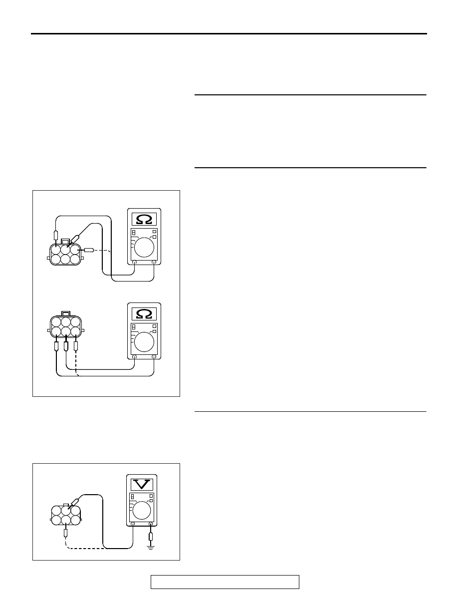
STEP 2. Measure the EGR valve motor coil resistance.
(1) Disconnect the EGR valve connector B-12.
(2) Measure the resistance between EGR valve connector 

terminal No. 2 and either terminal No. 1 or terminal No. 3.

Standard value: 20 

 24 ohms [at 20°C (68°F)]

(3) Measure the resistance between EGR valve connector 

terminal No. 5 and either terminal No. 4 or terminal No. 6

Standard value: 20 

 24 ohms [at 20°C (68°F)]

Q: Is the measured resistance between 20 and 24 ohms [at 

20

°C (68°F)]?

YES : Go to Step 3.
NO :  Replace the EGR valve. Then go to Step 11.

STEP 3. Measure the power supply voltage at EGR valve 
harness side connector B-12.
(1) Disconnect the connector B-12 and measure at the harness 

side.

(2) Turn the ignition switch to the "ON" position.
(3) Measure the voltage between terminal No. 2, No. 5 and 

ground.

• Voltage should be battery positive voltage.

(4) Turn the ignition switch to the "LOCK" (OFF) position.
Q: Is battery positive voltage (approximately 12 volts) 

present?
YES : 
Go to Step 5.
NO :  Go to Step 4.

1

2 3

4

5 6

1

2 3

4

5 6

AK604459 AB

1

2

3

4

5

6

AK201419

B-12 harness 
connector: 
component side

AK

MULTIPORT FUEL INJECTION (MFI) DIAGNOSIS

TSB Revision

MULTIPORT FUEL INJECTION (MFI) <2.4L ENGINE>

13A-504

STEP 4. Check harness connector A-33X at MFI relay for 
damage.
Q: Is the harness connector in good condition?

YES : Check harness connector A-13 at intermediate 

connector for damage, and repair or replace as 
required. Refer to GROUP 00E, Harness Connector 
Inspection 

P.00E-2

. If intermediate connector is in 

good condition, repair harness wire between MFI 
relay connector A-33X (terminal No. 2) and EGR 
valve connector B-12 (terminal No. 2, No. 5) because 
of open circuit or short circuit to ground. Then go to 
Step 11.

NO :  Repair or replace it. Refer to GROUP 00E, Harness 

Connector Inspection 

P.00E-2

. Then go to Step 11.

STEP 5. Check harness connector B-10 at ECM for 
damage.
Q: Is the harness connector in good condition?

YES : Go to Step 6.
NO :  Repair or replace it. Refer to GROUP 00E, Harness 

Connector Inspection 

P.00E-2

. Then go to Step 11.

MULTIPORT FUEL INJECTION (MFI) DIAGNOSIS

TSB Revision

MULTIPORT FUEL INJECTION (MFI) <2.4L ENGINE>

13A-505

STEP 6. Measure the power supply voltage at ECM 
connector B-10 by using power plant ECU check harness 
special tool MB992110.
(1) Disconnect all ECM connectors. Connect the power plant 

ECU check harness special tool MB992110 between the 
separated connectors.

(2) Measure the voltage between terminal (No. 31, No. 32, No. 

47, No. 48) and ground.

• The voltage should be between 5 and 8 volts for approx-

imately 3 seconds when the Ignition switch is turned 
from the "LOCK" (OFF) position to the "ON" position.

(3) Turn the ignition switch to the "LOCK" (OFF) position.
Q: Is the voltage normal?

YES : Go to Step 8.
NO :  Go to Step 7.

AK604040

ECM

AB

Body side harness 

MB992110

AK604827

16 15 14 13 12 11 10 9 8 7 6 5 4 3

2

1

32 31 30 29 28 27 26 25 24 23 22 21 20 19 18 17

48 47 46 45 44 43 42 41 40 39 38 37 36 35 34 33

64 63 62 61 60 59 58 57 56 55 54 53 52 51 50 49

AB

Power plant ECU
check harness connector

MULTIPORT FUEL INJECTION (MFI) DIAGNOSIS

TSB Revision

MULTIPORT FUEL INJECTION (MFI) <2.4L ENGINE>

13A-506

STEP 7. Check for open circuit and short circuit to ground 
between EGR valve connector B-12 and ECM connector 
B-10.

a. EGR valve connector B-12 (terminal No. 1) and ECM con-

nector B-10 (terminal No. 31).

b. EGR valve connector B-12 (terminal No. 3) and ECM con-

nector B-10 (terminal No. 32).

c. EGR valve connector B-12 (terminal No. 4) and ECM con-

nector B-10 (terminal No. 47). 

d. EGR valve connector B-12 (terminal No. 6) and ECM con-

nector B-10 (terminal No. 48).

Q: Is the harness wire in good condition?

YES : Replace the ECM. When the ECM is replaced, 

register the ID code. Refer to GROUP 42B, Diagnosis 
− ID Code Registration Judgment Table <Vehicles 

with KOS> 

P.42B-15

 or GROUP 42C, Diagnosis 

− ID 

Codes Registration Judgment Table <Vehicles with 
WCM> 

P.42C-10

. Then go to Step 11.

NO :  Repair it. Then go to Step 11.

STEP 8. Check the EGR valve operation using special tool 
MB991658.
(1) Remove the EGR valve.
(2) Connect special tool MB991658 to the EGR valve. (All 

terminals should be connected.)

(3) Use the jumper wires to connect terminal No. 2 of the EGR 

valve connector to the positive battery terminal.

(4) Check to ensure that the motor operates when the terminal 

No. 1 and No. 3 of the EGR valve connector are 
respectively connected to the negative battery terminal 
using a jumper wire.

• Vibration should be present at each application of volt-

age to test clip combination.

(5) Then, use jumper wires to connect the terminal No. 5 of the 

EGR valve connector to the positive battery terminal.

(6) Check to ensure that the motor operates when terminal No. 

4 and No. 6 of the EGR valve connector are respectively 
connected to the negative battery terminal using a jumper 
wire.

• Vibration should be present at each application of volt-

age to test clip combination.

(7) Reinstall the EGR valve, using a new gasket, and tighten to 

the specified torque.

Tighten torque: 24 

± 3 Nm [17 ± 3 ftIb]

Q: Is the EGR valve operating properly?

YES : Go to Step 9.
NO :  Replace the EGR valve. Then go to Step 11.

AK203699

+

-

AC

Battery

MB991658


Content   ..  668  669  670  671   ..