Mitsubishi Outlander GS45X. Manual - part 668
MULTIPORT FUEL INJECTION (MFI) DIAGNOSIS
TSB Revision
MULTIPORT FUEL INJECTION (MFI) <2.4L ENGINE>
13A-495
DTC P0462: Fuel Level Sensor <FWD> or Fuel Level Sensor (main) <AWD> Circuit Low Input
.
TECHNICAL DESCRIPTION
• The fuel level sensor converts the rest of the fuel
to a voltage and sends it to the combination
meter.
• The combination meter sends the data regarding
the rest of the fuel to the ECM.
• The ECM checks whether this data is within a
specified range.
.
DESCRIPTIONS OF MONITOR METHODS
A short circuit is detected while monitoring the fuel
level sensor output.
.
MONITOR EXECUTION
Continuous
.
MONITOR EXECUTION CONDITIONS
(Other monitor and Sensor)
Other Monitor (There is no temporary DTC stored
in memory for the item monitored below)
• Not applicable
Sensor (The sensor below is determined to be
normal)
• Not applicable
.
DTC SET CONDITIONS
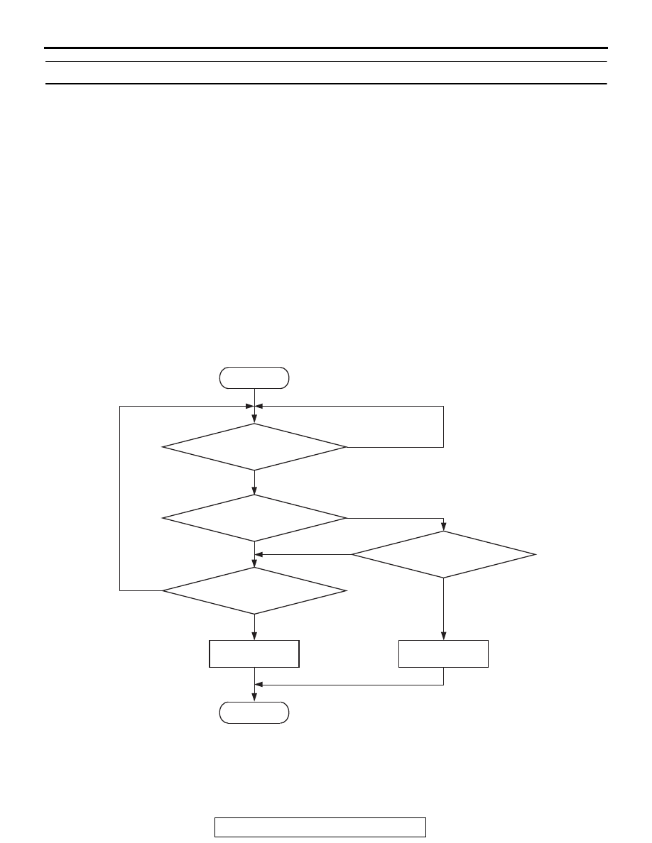
Logic Flow Chart
.
Check Conditions
• Battery positive voltage is between 11 and 16.5
volts.
• 2 seconds or more have passed since the engine
staring sequence was completed.
AK604342
Good
Malfunction
End
No
No
No
No
Fuel level sensor
resistance <= 2 ohms
Fuel level sensor
resistance >= 186 ohms
Start
Continuous
failure for 2secs
Monitoring
conditions
Yes
Yes
Yes
Yes