Mitsubishi Outlander GS45X. Manual - part 650


  Index      Mitsubishi     Mitsubishi Outlander GS45X - service repair manual


Search            


Content   ..  648  649  650  651   ..


Mitsubishi Outlander GS45X. Manual - part 650


MULTIPORT FUEL INJECTION (MFI) DIAGNOSIS

TSB Revision

MULTIPORT FUEL INJECTION (MFI) <2.4L ENGINE>

13A-423

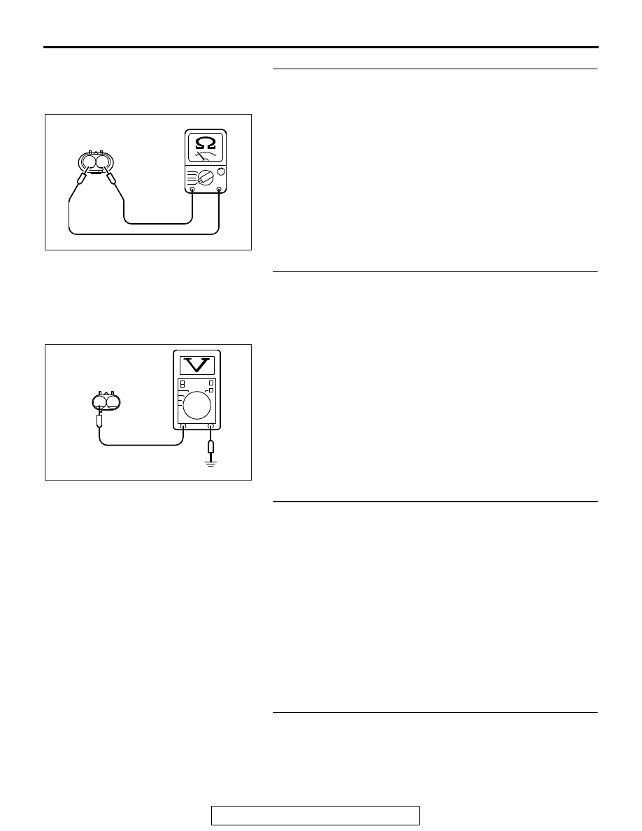
STEP 3. Check the evaporative emission purge solenoid.
(1) Disconnect the evaporative emission purge solenoid 

connector B-07.

(2) Measure the resistance between evaporative emission 

purge solenoid side connector terminal No. 1 and No. 2.

Standard value: 22 

 26 ohms [at 20°C (68°F)]

Q: Is the measured resistance between 22 and 26 ohms [at 

20

°C (68°F)]?

YES : Go to Step 4.
NO :  Replace the evaporative emission purge solenoid. 

Then go to Step 10.

STEP 4. Measure the power supply voltage at evaporative 
emission purge solenoid harness side connector B-07.
(1) Disconnect the connector B-07 and measure at the harness 

side.

(2) Turn the ignition switch to the "ON" position.
(3) Measure the voltage between terminal No. 2 and ground.

• Voltage should be battery positive voltage.

(4) Turn the ignition switch to the "LOCK" (OFF) position.
Q: Is battery positive voltage (approximately 12 volts) 

present?
YES : 
Go to Step 6.
NO :  Go to Step 5.

STEP 5. Check harness connector A-33X at MFI relay for 
damage.
Q: Is the harness connector in good condition?

YES : Check harness connector A-13 at intermediate 

connector for damage, and repair or replace as 
required. Refer to GROUP 00E, Harness Connector 
Inspection 

P.00E-2

. If intermediate connector is in 

good condition, repair harness wire between MFI 
relay connector A-33X (terminal No. 2) and 
evaporative emission purge solenoid connector B-07 
(terminal No. 2) because of open circuit or short 
circuit to ground. Then go to Step 10.

NO :  Repair or replace it. Refer to GROUP 00E, Harness 

Connector Inspection 

P.00E-2

. Then go to Step 10.

STEP 6. Check harness connector B-10 at the ECM for 
damage.
Q: Is the harness connector in good condition?

YES : Go to Step 7.
NO :  Repair or replace it. Refer to GROUP 00E, Harness 

Connector Inspection 

P.00E-2

. Then go to Step 10.

1 2

AK202961

Evaporative emission
purge solenoid connector

AC

AK303144

1

2

B-07 harness 
connector: 
component side

AD

MULTIPORT FUEL INJECTION (MFI) DIAGNOSIS

TSB Revision

MULTIPORT FUEL INJECTION (MFI) <2.4L ENGINE>

13A-424

STEP 7. Measure the power supply voltage at ECM 
connector B-10 by using power plant ECU check harness 
special tool MB992110.
(1) Disconnect all ECM connectors. Connect the power plant 

ECU check harness special tool MB992110 between the 
separated connectors.

(2) Turn the ignition switch to the "ON" position.

(3) Measure the voltage between terminal No. 37 and ground.

• Voltage should be battery positive voltage.

(4) Turn the ignition switch to the "LOCK" (OFF) position.
Q: Is battery positive voltage (approximately 12 volts) 

present?
YES : 
Go to Step 8.
NO :  Repair harness wire between evaporative emission 

purge solenoid connector B-07 (terminal No. 1) and 
ECM connector B-10 (terminal No. 37) because of 
open circuit or short circuit to ground. Then go to Step 
10.

STEP 8. Check for harness damage between MFI relay 
connector A-33X (terminal No. 2) and evaporative emission 
purge solenoid connector B-07 (terminal No. 2).
NOTE: Check harness connector after checking intermediate 
connector A-13. If intermediate connector is damaged, repair or 
replace it. Refer to GROUP 00E, Harness Connector Inspec-
tion 

P.00E-2

. Then go to Step 10.

Q: Is the harness wire in good condition?

YES : Go to Step 9.
NO :  Repair it. Then go to Step 10.

AK604040

ECM

AB

Body side harness 

MB992110

AK604209

16 15 14 13 12 11 10 9 8 7 6 5 4 3

2

1

32 31 30 29 28 27 26 25 24 23 22 21 20 19 18 17

48 47 46 45 44 43 42 41 40 39 38 37 36 35 34 33

64 63 62 61 60 59 58 57 56 55 54 53 52 51 50 49

AB

Power plant ECU
check harness connector

MULTIPORT FUEL INJECTION (MFI) DIAGNOSIS

TSB Revision

MULTIPORT FUEL INJECTION (MFI) <2.4L ENGINE>

13A-425

STEP 9. Check for harness damage between evaporative 
emission purge solenoid connector B-07 (terminal No. 1) 
and ECM connector B-10 (terminal No. 37).
Q: Is the harness wire in good condition?

YES : Replace the ECM. When the ECM is replaced, 

register the ID code. Refer to GROUP 42B, Diagnosis 
− ID Code Registration Judgment Table <Vehicles 

with KOS> 

P.42B-15

 or GROUP 42C, Diagnosis 

− ID 

Codes Registration Judgment Table <Vehicles with 
WCM> 

P.42C-10

. Then go to Step 10.

NO :  Repair it. Then go to Step 10.

STEP 10. Test the OBD-II drive cycle.
(1) Carry out a test drive with the drive cycle pattern. Refer to 

Diagnostic Function 

− OBD-II Drive Cycle − Pattern 23 

P.13A-11

.

(2) Check the diagnostic trouble code (DTC).
Q: Is DTC P0443 set?

YES : Retry the troubleshooting.
NO :  The inspection is complete.

MULTIPORT FUEL INJECTION (MFI) DIAGNOSIS

TSB Revision

MULTIPORT FUEL INJECTION (MFI) <2.4L ENGINE>

13A-426

DTC P0446: Evaporative Emission Control System Vent Control Circuit

AK704133

1

3

2

4

2

8

7

6

5

4

3

11

21

20

19

18

17

16

15

14

13

12

9

22

1

10

2

1

71 72 73 74 75 76 77 78 79 80 81 82

83 84 85 86 87 88 89 90 91 92 93 94

95 96 97 98 99

100 101 102 103 104

112 113 114

109

108

107

110 111

115 116

106

105

118

117

3 4

2

1

C-129

117

8

1

D-113

B-11

20A

WHITE

WHITE

GREEN

GREEN

GREEN

WHITE

A-33X

4

3

1

2

22

OFF

ON

AB

EVAPORATIVE EMISSION VENTILATION SOLENOID CIRCUIT

EVAPORATIVE EMISSION
VENTILATION SOLENOID

D-116

(MU802779)

1

36

FUSIBLE LINK

WHITE

WHITE

2

2

1

RELAY BOX
(ENGINE COMPARTMENT)

ENGINE CONTROL MODULE

MFI
RELAY

TO ECM


Content   ..  648  649  650  651   ..