Mitsubishi Outlander GS45X. Manual - part 615


  Index      Mitsubishi     Mitsubishi Outlander GS45X - service repair manual


Search            


Content   ..  613  614  615  616   ..


Mitsubishi Outlander GS45X. Manual - part 615


MULTIPORT FUEL INJECTION (MFI) DIAGNOSIS

TSB Revision

MULTIPORT FUEL INJECTION (MFI) <2.4L ENGINE>

13A-283

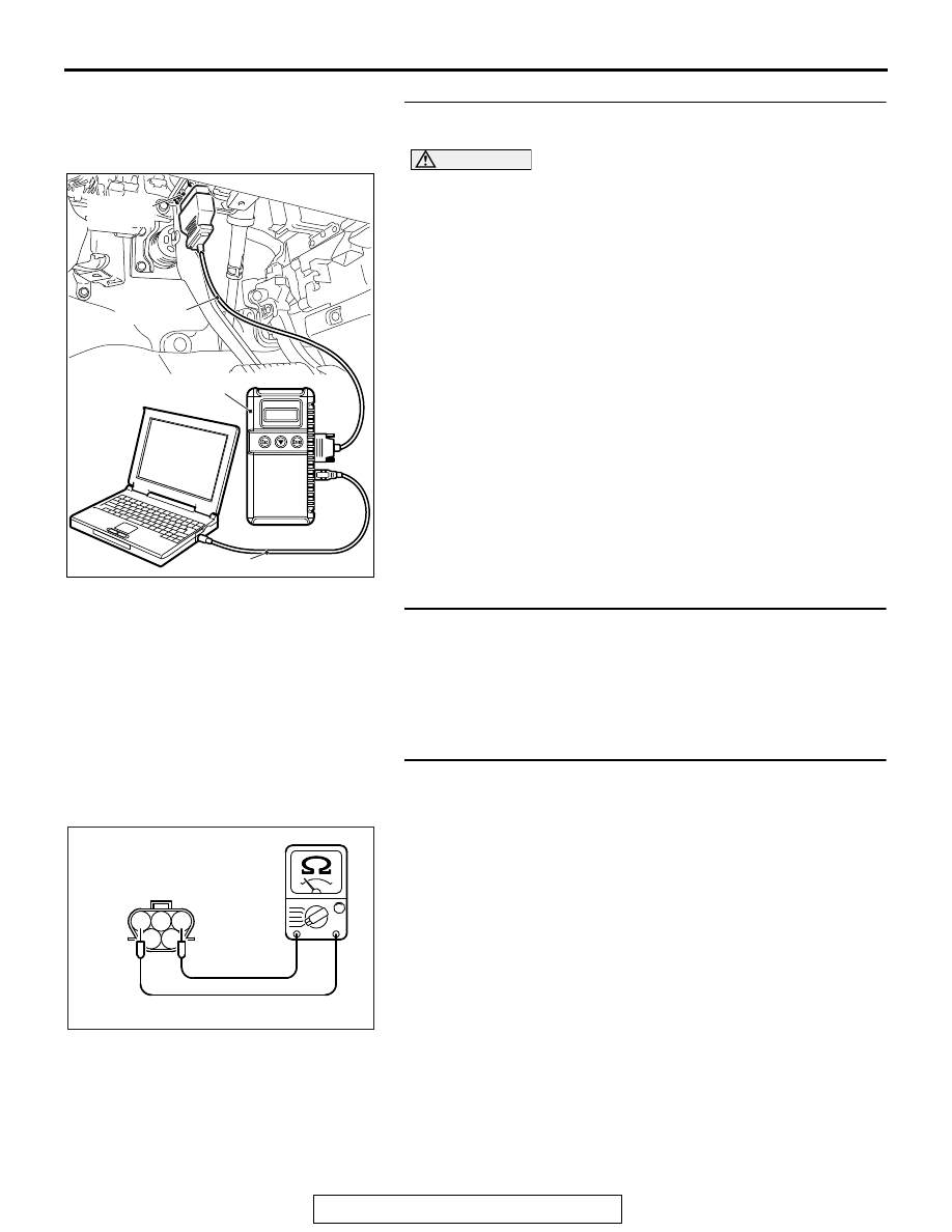
STEP 1. Using scan tool MB991958, check data list item 53: 
Fuel Tank Temperature Sensor.

CAUTION

To prevent damage to scan tool MB991958, always turn the 
ignition switch to the "LOCK" (OFF) position before con-
necting or disconnecting scan tool MB991958.
(1) Connect scan tool MB991958 to the data link connector.
(2) Turn the ignition switch to the "ON" position.
(3) Set scan tool MB991958 to the data reading mode for item 

53, Fuel Tank Temperature Sensor.

• Approximately the same as the ambient air temperature 

when the engine is cooled.

(4) Turn the ignition switch to the "LOCK" (OFF) position.
Q: Is the sensor operating properly?

YES : It can be assumed that this malfunction is intermittent. 

Refer to GROUP 00, How to Use 
Troubleshooting/Inspection Service Points 

− How to 

Cope with Intermittent Malfunctions 

P.00-15

.

NO :  Go to Step 2.

STEP 2. Check harness connector D-20 at the fuel tank 
temperature sensor for damage.
Q: Is the harness connector in good condition?

YES : Go to Step 3. 
NO :  Repair or replace it. Refer to GROUP 00E, Harness 

Connector Inspection 

P.00E-2

. Then go to Step 6.

STEP 3. Check the fuel tank temperature sensor.
(1) Disconnect the fuel tank temperature sensor connector 

D-20.

(2) Measure the resistance between terminal No. 1 and No. 3 

of the fuel tank temperature sensor.

Standard value: 0.5 

 12.0 kΩ

Q: Is the measured resistance between 0.5 and 12.0 k

Ω?

YES : Go to Step 4.
NO :  Replace the fuel tank temperature sensor. Then go to 

Step 6.

AK700568AB

MB991824

MB991827

MB991910

Data link
connector

1

2 3

4

5

AK203165

Fuel tank temperature
sensor connector

AC

MULTIPORT FUEL INJECTION (MFI) DIAGNOSIS

TSB Revision

MULTIPORT FUEL INJECTION (MFI) <2.4L ENGINE>

13A-284

STEP 4. Check harness connector B-11 at ECM for 
damage.
Q: Is the harness connector in good condition?

YES : Go to Step 5.
NO :  Repair or replace it. Refer to GROUP 00E, Harness 

Connector Inspection 

P.00E-2

. Then go to Step 6.

STEP 5. Check for short circuit to ground between fuel 
tank temperature sensor connector D-20 (terminal No. 3) 
and ECM connector B-11 (terminal No. 115).
NOTE: Check harness after checking intermediate connector 
C-129. If the intermediate connector is damaged, repair or 
replace it. Refer to GROUP 00E, Harness Connector Inspec-
tion 

P.00E-2

. Then go to Step 6.

Q: Is the harness wire in good condition?

YES : Replace the ECM. When the ECM is replaced, 

register the ID code. Refer to GROUP 42B, Diagnosis 
− ID Code Registration Judgment Table <Vehicles 

with KOS> 

P.42B-15

 or GROUP 42C, Diagnosis 

− ID 

Codes Registration Judgment Table <Vehicles with 
WCM> 

P.42C-10

. Then go to Step 6.

NO :  Repair it. Then go to Step 6.

STEP 6. Test the OBD-II drive cycle.
(1) Carry out a test drive with the drive cycle pattern. Refer to 

Diagnostic Function 

− OBD-II Drive Cycle − Pattern 23 

P.13A-11

.

(2) Check the diagnostic trouble code (DTC).
Q: Is DTC P0182 set?

YES : Retry the troubleshooting.
NO :  The inspection is complete.

MULTIPORT FUEL INJECTION (MFI) DIAGNOSIS

TSB Revision

MULTIPORT FUEL INJECTION (MFI) <2.4L ENGINE>

13A-285

DTC P0183: Fuel Tank Temperature Sensor Circuit High Input

1

2 3

4

5

AK704106

71 72 73 74 75 76 77 78 79 80 81 82

83 84 85 86 87 88 89 90 91 92 93 94

95 96 97 98 99

100 101 102 103 104

112 113 114

109

108

107

110 111

115 116

106

105

118

117

2

8

7

6

5

4

3

11

21

20

19

18

17

16

15

14

13

12

9

22

1

10

AB

FUEL TANK TEMPERATURE  SENSOR  CIRCUIT

7

3

2

1

BLA

CK

D-20

(MU802058)

115

FUEL TANK TEMPERATURE
SENSOR (INTEGRATED IN FUEL
PUMP MODULE)

5 V

VIOLET

VIOLET

B-11

C-129

FROM
COMBNATION
METER

ENGINE
CONTROL
MODULE

AK704097AB

Connector: B-11

B-11 (GR)

AK900595

Connector: C-129

C-129

AB

MULTIPORT FUEL INJECTION (MFI) DIAGNOSIS

TSB Revision

MULTIPORT FUEL INJECTION (MFI) <2.4L ENGINE>

13A-286

.

CIRCUIT OPERATION

• 5-volt voltage is applied to the fuel tank tempera-

ture sensor output terminal (terminal No. 3) from 
the ECM (terminal No. 115) via the resistor in the 
ECM.

• The fuel tank temperature sensor output voltage 

increases when the resistance increases and 
decreases when the resistance decreases. The 
ground terminal (terminal No. 1) is grounded to 
the vehicle body.

.

TECHNICAL DESCRIPTION

• The fuel tank temperature sensor converts the 

fuel tank temperature to a voltage.

• The ECM detects the fuel tank temperature with 

this output voltage.

.

DESCRIPTIONS OF MONITOR METHODS

Fuel tank temperature sensor output voltage is out of 

specified range.

.

MONITOR EXECUTION

Continuous

.

MONITOR EXECUTION CONDITIONS 
(Other monitor and Sensor)

Other Monitor (There is no temporary DTC stored 

in memory for the item monitored below)

• Not applicable

Sensor (The sensor below is determined to be 

normal)

• Not applicable

.

AK704107

AB

Fuel tank differential 
pressure sensor

Fuel pump module (incorporating 
fuel level sensor (main) and 
fuel tank temperature sensor)

Connector: D-20

D-20 (GR)


Content   ..  613  614  615  616   ..