Mitsubishi Outlander GS45X. Manual - part 575
MULTIPORT FUEL INJECTION (MFI) DIAGNOSIS
TSB Revision
MULTIPORT FUEL INJECTION (MFI) <2.4L ENGINE>
13A-123
DTC SET CONDITIONS <Range/Performance problem
− high>
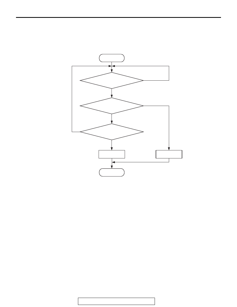
Logic Flow Chart
Check Conditions
• Throttle position sensor output voltage is 0.8 volt
or lower.
• Mass airflow sensor output voltage is 4.9 volts
(corresponding to an air flow rate of 295 g/sec) or
lower.
Judgement Criterion
• Mass airflow sensor output voltage has continued
to be 2.5 volts (corresponding to an air flow rate
of 28 g/sec) or higher for 2 seconds.
.
End
No
No
No
Malfunction
Good
Output voltage
>= 2.5 V
AK900353
Start
Yes
Yes
Yes
Continuous
failure for 2secs
Monitoring
conditions