Mitsubishi Outlander GS45X. Manual - part 563
MULTIPORT FUEL INJECTION (MFI) DIAGNOSIS
TSB Revision
MULTIPORT FUEL INJECTION (MFI) <2.4L ENGINE>
13A-75
DTC SET CONDITIONS
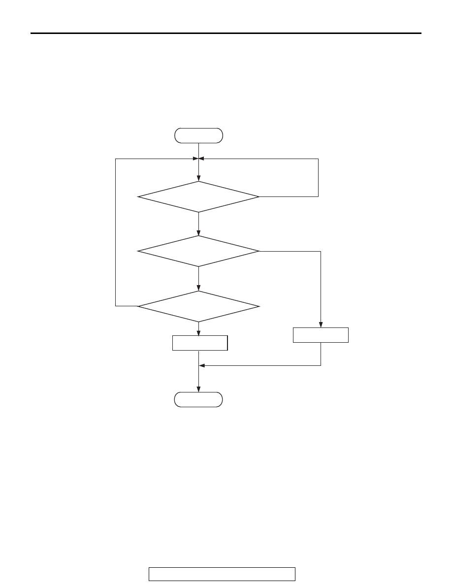
Logic Flow Chart
Check Conditions
• More than 20 seconds have passed since the
engine starting sequence was completed.
• Engine speed is 1,188 r/min or more.
• Engine coolant temperature is higher than 76°C
(169
°F).
Judgment Criterion
• The difference between the actual exhaust valve
closing timing and the exhaust valve target clos-
ing timing is more than 5 degrees for 5 seconds.
.
OBD-II DRIVE CYCLE PATTERN
• Refer to Diagnostic Function − OBD-II Drive
Cycle
− Pattern 20
.
.
TROUBLESHOOTING HINTS (The most
likely causes for this code to be set are:)
• Exhaust engine oil control valve failed.
• Oil passage of variable valve timing control sys-
tem clogged.
• Exhaust variable valve timing sprocket operation
mechanism stuck.
• ECM failed.
AK604305
Start
Yes
Yes
Yes
No
No
No
|Cam angle-target|
> 5˚CA
Continuous
failure for 5secs
Malfunction
End
Good
Monitoring
conditions