Mitsubishi Outlander GS45X. Manual - part 524
EXHAUST PIPE AND MAIN MUFFLER
TSB Revision
INTAKE AND EXHAUST
15-23
Required Special Tool:
• MB991953: Oxygen Sensor Wrench
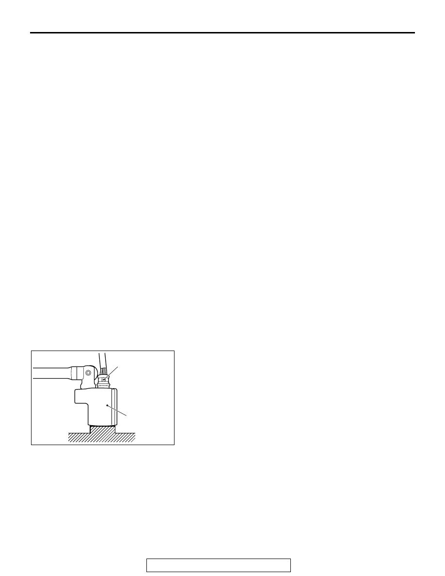
REMOVAL SERVICE POINTS
.
<<A>> LINER AIR-FUEL RATIO SENSOR/HEATED
OXYGEN SENSOR REMOVAL
Remove the connection and clamp of linear air-fuel ratio sensor
connector or heated oxygen sensor connector, and then use
special tool MB991953 to remove the linear air-fuel ratio sensor
or heated oxygen sensor.
.
Exhaust main muffler and rear
floor panel heat protector
removal steps
1.
Exhaust main muffler
10. Seal ring
11. Exhaust muffler hanger
>>
C
<<
12. Exhaust tail pipe diffuser
16. Rear floor panel heat protector
Center exhaust pipe and front
floor panel rear heat protector
removal steps
2.
Backbone brace
•
Lower side cover (RH) (Refer to
GROUP 52A, Front Floor
Console Assembly
).
•
Turn up the passenger's side floor
carpet.
3.
Linear air-fuel ratio sensor
connection
<<
A
>>
>>
B
4.
Linear air-fuel ratio sensor
5.
Harness cover
•
Front seat assembly (RH) (Refer
to GROUP 52A, Front Seat
Assembly
6.
Heated oxygen sensor connector
connection
<<
A
>>
>>
B
<<
7.
Heated oxygen sensor
8.
Center exhaust pipe
10. Seal ring
13. Exhaust pipe gasket
14. Exhaust muffler hanger
<<
B
>>
>>
A
<<
17. Rivet
18. Front floor rear panel heat
protector
Front exhaust pipe and front
floor panel front heat protector
removal steps
9.
Front exhaust pipe
13. Exhaust pipe gasket
15. Seal ring
19. Dash panel heat protector
<<
B
>>
>>
A
<<
20. Rivet
21. Front floor front panel heat
protector
Center exhaust pipe and front
floor panel rear heat protector
removal steps (Continued)
AC703721
MB991953
AC
Linear air-fuel ratio
sensor or heated
oxygen sensor