Mitsubishi Outlander GS45X. Manual - part 512
GENERAL INFORMATION
TSB Revision
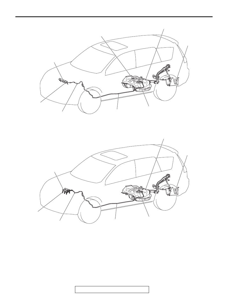
FUEL SUPPLY
13C-3
<3.0L ENGINE>
AC901401
Fuel injector
Fuel rail
Fuel pipe
Fuel pump module
Evaporative
emission
canister
AB
Fuel tank
Fuel level sensor (sub)
<AWD>
Fuel high-pressure hose
AC901402
Fuel injector
Fuel rail
Fuel pipe
Fuel pump module
AC
Fuel tank
<FWD>
Fuel high-pressure hose
Evaporative
emission
canister