Mitsubishi Outlander GS45X. Manual - part 475


  Index      Mitsubishi     Mitsubishi Outlander GS45X - service repair manual


Search            


Content   ..  473  474  475  476   ..


Mitsubishi Outlander GS45X. Manual - part 475


CAMSHAFT

TSB Revision

ENGINE MECHANICAL <2.4L ENGINE>

11A-31

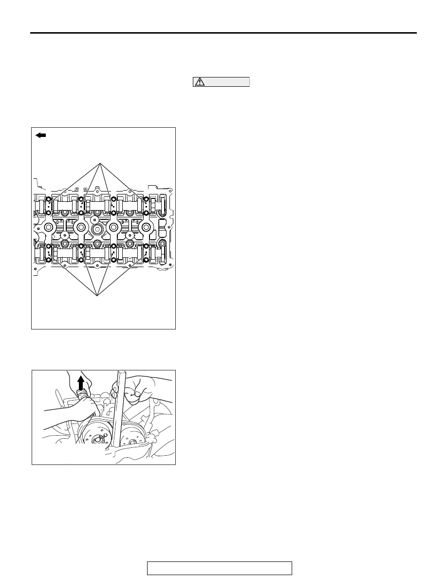
<<E>> CAMSHAFT BEARING OIL FEEDING 
CAP/CAMSHAFT BEARING CAP/CAMSHAFT 
BEARING THRUST CAP REMOVAL

CAUTION

When the camshaft bearing cap mounting bolts are loos-
ened at once, the mounting bolts jump out by the spring 
force and the threads are damaged. Always loosen the 
mounting bolts in four or five steps.
Loosen the mounting bolts of the camshaft bearing caps in the 
order of number shown in the figure in four or five steps, and 
remove the camshaft bearing caps.

.

<<F>> CAMSHAFT AND CAMSHAFT SPROCKET 
ASSEMBLY (EXHAUST SIDE) REMOVAL

1. Raise slightly the transaxle side of the camshaft and 

camshaft sprocket assembly (exhaust side) by using the 
slack of the timing chain, and remove from the cam bearing.

AC506746

AC

1

1

2

2

3

3

4

4

5

5

6

6

7

7

8

8

Engine front

Camshaft bearing cap

Camshaft bearing cap

AC508124AD

Camshaft and camshaft 
sprocket assembly

CAMSHAFT

TSB Revision

ENGINE MECHANICAL <2.4L ENGINE>

11A-32

2. Remove the timing chain from the camshaft and camshaft 

sprocket assembly (exhaust side) toward the timing chain 
case assembly, and remove the camshaft and camshaft 
sprocket assembly (exhaust side) toward the transaxle.

3. Remove special tool MB992103 inserted into the timing 

chain case assembly.

CAUTION

The timing chain may snag on other parts. After removing 
the camshaft and camshaft sprocket assembly, never 
rotate the crankshaft.
4. After removing the camshaft and camshaft sprocket 

assembly (exhaust side), hang up the timing chain with a 
rope to prevent the timing chain from falling into the timing 
chain case assembly.

.

<<G>> CAMSHAFT SPROCKET/CAMSHAFT 
REMOVAL

Hold the flats of the camshaft with a monkey wrench. Loosen 
the camshaft sprocket mounting bolts and remove the camshaft 
sprocket from the camshaft.

.

AC506749

AC

MB992103

Timing chain

Camshaft and
camshaft sprocket
assembly

AC509403

AD

Rope

Timing chain

AC700424AD

Hexagon part 
of camshaft

CAMSHAFT

TSB Revision

ENGINE MECHANICAL <2.4L ENGINE>

11A-33

<<H>> POWER STEERING OIL PUMP ASSEMBLY 
REMOVAL

1. With the hose installed, remove the power steering oil pump 

assembly from the bracket.

2. Tie the removed power steering oil pump assembly with a 

string at a position where it will not interfere with the removal 
and installation of oil control valve.

.

<<I>> OIL FEEDER CONTROL VALVE REMOVAL

CAUTION

After removal of the oil feeder control valve, be careful to 
prevent dust from getting into the oil passage in the cylin-
der head.

INSTALLATION SERVICE POINTS

.

>>A<< O-RING/OIL FEEDER CONTROL VALVE 
INSTALLATION

CAUTION

When installing the oil feeder control valve, be careful to 
avoid damage to the O-ring.
Apply engine oil to the O-ring of the oil feeder control valve and 
install the oil feeder control valve to the cylinder head.

.

>>B<< CAMSHAFT/CAMSHAFT SPROCKET 
INSTALLATION

1. Use a monkey wrench to secure the flats of the camshaft in 

the same manner as removal.

2. Apply an adequate and minimum amount of engine oil to the 

camshaft and camshaft sprocket as shown in the figure.

3. Install the camshaft sprocket to the camshaft.
4. Apply an adequate and minimum amount of engine oil to the 

camshaft sprocket bolt.

5. Tighten the camshaft sprocket bolt to the specified torque.

Tightening torque: 59 

± 5 Nm (44 ± 3 ft-lb)

.

AC611532AB

Hexagon part 
of camshaft

AC607720AB

Camshaft

Camshaft 
sprocket

Camshaft 
sprocket bolt

CAMSHAFT

TSB Revision

ENGINE MECHANICAL <2.4L ENGINE>

11A-34

>>C<< CAMSHAFT AND CAMSHAFT SPROCKET 
ASSEMBLY (INTAKE SIDE) INSTALLATION

1. Align the intake side paint mark of the timing chain which 

was put at removal with the paint mark of the intake side 
camshaft sprocket, and install the camshaft sprocket to the 
timing chain.

2. Install the camshaft and camshaft sprocket assembly (intake 

side) to the cylinder head.

.

>>D<< CAMSHAFT BEARING THRUST 
CAP/CAMSHAFT BEARING CAP/CAMSHAFT 
BEARING OIL FEEDING CAP/CAMSHAFT 
BEARING INSTALLATION

1. Install the camshaft bearing caps to the cylinder head.

NOTE: Because the camshaft bearing thrust cap and cam-
shaft bearing cap are the same in shape, check the bearing 
cap number and additionally its symbol to identify the intake 
and exhaust sides for correct installation.

2. Tighten each camshaft bearing cap mounting bolt to the 

specified torque in the order of number shown in the figure 
in two or three steps.

Tightening torque: 12 

± 1 Nm (107 ± 8 in-lb)

.

AC509403

AE

Paint markings
(intake side)

AC506778

AC

8

8

7

7

6

6

5

5

4

4

3

3

2

2

1

1

E  5

Engine front

Camshaft bearing cap

Camshaft bearing cap

Bearing cap No.

Identification of intake side 
and exhaust side


Content   ..  473  474  475  476   ..