Mitsubishi Outlander GS45X. Manual - part 470


  Index      Mitsubishi     Mitsubishi Outlander GS45X - service repair manual


Search            


Content   ..  468  469  470  471   ..


Mitsubishi Outlander GS45X. Manual - part 470


ON-VEHICLE SERVICE

TSB Revision

ENGINE MECHANICAL <2.4L ENGINE>

11A-11

2. Check the tension of the drive belt in the following 

procedures.

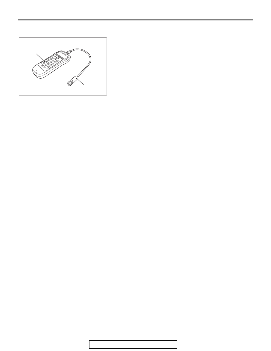
(1) Connect special tool MB992082 to special tool 

MB992081 of special tool MB992080.

(2) Press the "POWER" button to turn on the power supply.
(3) Press number key "1". Check to ensure that "No.01" 

appears on the upper left of the display and that the 
following numeric values are displayed for individual 
items (M, W, and S):
M 000.9 g/m
W 010.0 mm/R
S 0100 mm
If numeric values have not been entered (new tool), set 
them according to the belt specifications as shown below. 
Once you set them, you do not have to set them again. 
The settings remain undeleted even after battery 
replacement.
NOTE: This operation is to temporarily set the preset 
data such as the belt specifications, because if the mea-
surement is taken without input of the belt specifications, 
conversion to tension value (N) cannot be made, result-
ing in judgement of error.
<Setting procedure>
a. Press down the "MASS" button till the belt mass select 

display appears.

b. Press the "UP" or "DOWN" button to select "01 1.5GT 

0.9" and press the "MEASURE" button to decide it.
Check to ensure that "M 000.9 g/m" is displayed.

c. Press the "WIDTH" button to change to the belt width 

input display.

d. Press number keys 0, 1, 0, and 0 sequentially, and 

press the "SELECT" button to apply them. Check to 
ensure that "W 010.0 mm/R" appears on the display.

e. Press the "SPAN" button to change to the span length 

input display.

f. Press number keys 0, 1, 0, and 0 sequentially, and 

press the "SELECT" button to apply them. Check to 
ensure that "S 0100 mm" appears on the display.

(4) Press "Hz" button twice to change the display to the 

frequency display (Hz.)

AC507219AD

MB992082

MB992081

Belt tension meter set (MB992080)

ON-VEHICLE SERVICE

TSB Revision

ENGINE MECHANICAL <2.4L ENGINE>

11A-12

CAUTION

• When measuring, make sure that the engine is cold.
• Measure after turning the crankshaft clockwise one 

turn or more.

• Do not allow any contaminants such as water or oil to 

get onto the microphone.

• If strong gusts of wind blow against the microphone or 

if there are any loud sources of noise nearby, the val-
ues measured by the microphone may not correspond 
to actual values.

• If the microphone is touching the belt while the mea-

surement is being made, the values measured by the 
microphone may not correspond to actual values.

• Do not take the measurement while the vehicle's engine 

is running.

(5) Hold special tool MB992080 to the middle of the belt 

between the pulleys (at the place indicated by arrow) 
where it does not contact the belt [approximately 10 

− 15 

mm (0.4 

− 0.59 inch) away from the rear surface of the 

belt] so that it is perpendicular to the belt (within an angle 
of 

± 15 degree angle.)

(6) Press the "MEASURE" button.
(7) Gently tap the middle of the belt between the pulleys (the 

place indicated by the arrow) with your finger as shown in 
the illustration, and check that the vibration frequency of 
the belt is within the standard value.

Standard value: 102 

 129 Hz

NOTE: To take the measurement repeatedly, tap the belt 
again.

(8) Press and hold the "POWER" button to turn off the power 

supply.

3. If not within the standard value, replace the auto-tensioner 

(Refer to 

P.11A-67

.)

.

AC607321

AD

MB992080

15˚

Gently tap with your finger

15˚

10 – 15 mm
(0.4 – 0.59 inch)

Generator
pulley

Idler pulley

Idler pulley

Crankshaft 
pulley

Power steering
oil pump pulley

ON-VEHICLE SERVICE

TSB Revision

ENGINE MECHANICAL <2.4L ENGINE>

11A-13

<When using a tension gauge>

1. Check the tension of the drive belt (Refer to 

P.11A-9

.)

CAUTION

• When measuring, make sure that the engine is cold.
• Measure after turning the crankshaft clockwise one 

turn or more.

2. Use a belt tension gauge in the middle of the belt between 

the pulleys shown in the figure (at the place indicated by the 
arrow) to check that the belt tension is within the standard 
value.

Standard value: 248 

 400 N (56  90 lb)

3. If not within the standard value, replace the auto-tensioner 

(Refer to 

P.11A-67

.)

VALVE CLEARANCE CHECK AND ADJUSTMENT

M1111001501112

Refer to GROUP00, General 

− Maintenance service − Intake 

And Exhaust Valve Clearance (Inspect And Adjust)

IGNITION TIMING CHECK

M1111001702540

Required Special Tool:
MB991958: Scan Tool (M.U.T.-III Sub Assembly)

• MB991824: V.C.I.

• MB991827: M.U.T.-III USB Cable

• MB991910: M.U.T.-III Main Harness A

1. Before inspection, set the vehicle in the following condition:

• Engine coolant temperature: 80 − 95°C (176 − 203°F)

• Lights and all accessories: OFF

• Transaxle: P range

NOTE: On vehicles for Canada, the headlight, taillight, etc. 
remain lit even when the lighting switch is in "OFF" position 
but this is no problem for checks.

AC506733

AD

Generator
pulley

Idler pulley

Idler pulley

Crankshaft 
pulley

Power steering
oil pump pulley

Belt 
tension 
gauge 

ON-VEHICLE SERVICE

TSB Revision

ENGINE MECHANICAL <2.4L ENGINE>

11A-14

CAUTION

To prevent damage to scan tool MB991958, always turn the 
ignition switch to the "LOCK" (OFF) position before con-
necting or disconnecting scan tool MB991958.
2. Connect scan tool MB991958 to the data link connector.

3. Set the timing light to the power supply line (terminal No. 3) 

of the ignition coil No. 1.

4. Start the engine and run it at idle.
5. Check that the idle speed is approximately 650 r/min.
6. Select scan tool MB991958 actuator test "item number 11".
7. Check that basic ignition timing is within the standard value.

Standard value: 5

° BTDC ± 3°

8. If the basic ignition timing is not within the standard value, 

refer to GROUP 13A, Multiport Fuel Injection (MFI) <2.4L 
Engine> 

− Multiport Fuel Injection (MFI) Diagnosis − 

Symptom Chart 

P.13A-54

.  

CAUTION

If the actuator test is not canceled, the forced drive will 
continue for 27 minutes. Driving in this state could lead to 
engine failure.
9. Cancel the setting mode of the scan tool MB991958.
10.Check that the actual ignition timing is at the standard value.

Standard value: Approximately 10

° BTDC

NOTE: The ignition timing fluctuates about 

±

 7

°

, even under 

normal operating condition.
NOTE:  It is automatically further advanced by about 5

°

 from 

10

°

 Before Top Dead Center at higher altitudes.

NOTE: Wait till approximately 1 minute passes after the 
engine started, and check the ignition timing when the 
engine stabilized.

11.Remove the timing light.

AK800400

Data link
connector

MB991827

MB991824 

MB991910

AC

AK604618

3

2

1

3

2

1

AB

No. 1 ignition coil

Equipment side connector

Power supply line
(terminal No. 3)


Content   ..  468  469  470  471   ..