Mitsubishi Outlander GS45X. Manual - part 391


  Index      Mitsubishi     Mitsubishi Outlander GS45X - service repair manual


Search            


Content   ..  389  390  391  392   ..


Mitsubishi Outlander GS45X. Manual - part 391


ON-VEHICLE SERVICE

TSB Revision

ANTI-LOCK BRAKING SYSTEM (ABS)

35B-185

3. Confirm that the selector lever is in the "N" position, and 

then start the engine.

4. When carrying out the actuator tests No. 01 to 04, perform 

the actuator tests using scan tool while depressing the brake 
pedal. When carrying out the actuator tests, rotate the wheel 
by hands to confirm that the braking force changes.
NOTE: 

.

While performing the actuator test, the ABS warning light 
flashes at a rate of 2 Hz.

When ABS-ECU is disabled due to the fail-safe function, 
the scan tool actuator test cannot be performed.

After the actuator test has been performed, the ABS 
warning light and brake waning light illuminate until the 
ignition switch is turned to ON again or the communica-
tion between scan tool and ABS-ECU is terminated.

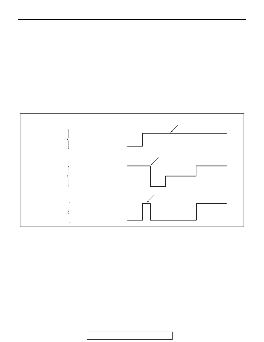
5. This is indicated as shown in the above.
6. When any malfunction has been found, take a necessary 

action according to the "Judgment Table."

AC608801

M.U.T.-III actuator test
(No.01, 02, 03, 04) start

M.U.T.-III actuator test
(No.01, 02, 03, 04)

M.U.T.-III actuator test
(No.01, 02, 03, 04)

Pedal operation

Depressed

Released

Solenoid valve position

Increase in pressure

Steady pressure

Reduction in pressure

Checking the brake force

Lock

Drag force when the pedal is free

Approx.
1 second

Approx.
2 seconds

Approx.
3 seconds

AC

ON-VEHICLE SERVICE

TSB Revision

ANTI-LOCK BRAKING SYSTEM (ABS)

35B-186

Judgment Table

7. After the inspection, turn the ignition switch to the LOCK 

(OFF) position, and then disconnect scan tool.

.

Hydraulic unit installation adjustment

Refer to 

P.35B-188

.

1. Operate the pre-removal steps for the hydraulic unit.
2. Remove all brake tubes.
3. Remove the protector.
4. Loosen the mounting bolt and nut of the hydraulic unit 

bracket.

5. Install all brake tubes temporarily.
6. Shake hydraulic unit to all directions with both hands to 

make the hydraulic unit bracket insulator fit with the unit.

7. Install the hydraulic unit bracket with mounting bolt and nut 

not to load the brake tube.

8. Install the protector.
9. Install all brake tubes securely.

NOTE: Install the flare nut taking care not to let the brake 
tube turn together.

10.Operate the post-installation steps of the hydraulic unit.

Display on 
scan tool

Operation

Inspection 
result

Judgme
nt

Probable cause

Remedy

01 FR wheel 
ABS
02 FL wheel 
ABS
03 RR wheel 
ABS
04 RL wheel 
ABS

• Depress the brake 

pedal to lock the 
vehicle.

• Select the vehicle 

to be inspected 
using scan tool, 
perform the 
actuator test.

• Rotate the selected 

wheel by hands to 
confirm the braking 
force.

Braking force 
decreases for 3 
seconds from 
the lock status.

Normal

The wheel 
does not lock 
even if the 
brake pedal is 
depressed.

Error

Clogged brake line 
other than hydraulic 
unit

Check and 
clean the brake 
line.

Clogged hydraulic 
circuit in the hydraulic 
unit

Replace the 
hydraulic unit 
assembly.

Braking force 
does not 
decrease.

Faulty routing of 
hydraulic unit brake 
tube

Route the 
brake tube 
correctly.

Malfunction of 
hydraulic unit solenoid 
valve operation

Replace the 
hydraulic unit 
assembly.

ON-VEHICLE SERVICE

TSB Revision

ANTI-LOCK BRAKING SYSTEM (ABS)

35B-187

IN THE EVENT OF A DISCHARGED BATTERY

M1352003500804

WARNING

If the ABS is not operating, the vehicle will be unsta-
ble during braking, Do not drive the vehicle with the 
ABS-ECU connector disconnected or with the ABS 
not operating.

If the engine is started using a booster cable when the battery 
is completely flat, and the vehicle is then driven without waiting 
for the battery to be recharged, the engine may misfire and it 
may not be possible to drive the vehicle. This is because the 
ABS consumes a large amount of current when carrying out its 
initial checks. If this happens, recharge the battery fully.

HYDRAULIC UNIT

TSB Revision

ANTI-LOCK BRAKING SYSTEM (ABS)

35B-188

HYDRAULIC UNIT

REMOVAL AND INSTALLATION

M1352008601069

NOTE: ABS-ECU is located in the hydraulic unit.

Pre-removal operation
• Strut tower bar removal (Refer to GROUP 42A − Strut 

Tower Bar 

P.42A-13

.)

• Brake fluid draining

• Intake manifold plenum removal (Refer to GROUP 15 − 

Intake Manifold Plenum 

P.15-6

.)

Post-installation operation
• Intake manifold plenum installation (Refer to GROUP 15 − 

Intake Manifold Plenum 

P.15-6

.)

• Brake fluid refilling and air bleeding (Refer to GROUP 35A 

− On-vehicle Service, Brake Fluid Level Inspection and 

Bleeding 

P.35A-20

.)

• Strut tower bar installation (Refer to GROUP 42A − Strut 

Tower Bar 

P.42A-13

.)

• Hydraulic unit check (Refer to 

P.35B-184

.)

AC703833 AB

5

1

11

5

10 ± 2 N·m
89 ± 17 in-lb

24 ± 4 N·m
18 ± 3 ft-lb

5

9

12

16 ± 3 N·m
12 ± 2 ft-lb

5

10

13 ± 2 N·m
111 ± 22 in-lb

3

8

4

5

2

6

7

Removal steps 

1.

ABS-ECU harness connector

2.

Suction pipe installation bolt

3.

Wheel speed sensor harness 
connector connection

4.

Wheel speed sensor harness clip 
connection

>>A<<

5.

Brake tube connection

6.

Brake tube and clip connection

7.

Suction pipe, liquid pipe and clip 
connection

8.

Hydraulic unit (ABS-ECU) and 
hydraulic unit bracket

<<A>>

9.

Hydraulic unit (ABS-ECU)

10. Hydraulic unit bracket insulator
11. Hydraulic unit bracket B
12. Hydraulic unit bracket A

Removal steps (Continued)


Content   ..  389  390  391  392   ..