Mitsubishi Outlander GS45X. Manual - part 377


  Index      Mitsubishi     Mitsubishi Outlander GS45X - service repair manual


Search            


Content   ..  375  376  377  378   ..


Mitsubishi Outlander GS45X. Manual - part 377


ABS DIAGNOSIS

TSB Revision

ANTI-LOCK BRAKING SYSTEM (ABS)

35B-129

STEP 9. Check the fuse No.12.
Visually check for open circuit in fuse No.12.
Q: Is the check result normal?

YES : Go to Step 11.
NO :  Go to Step 10.

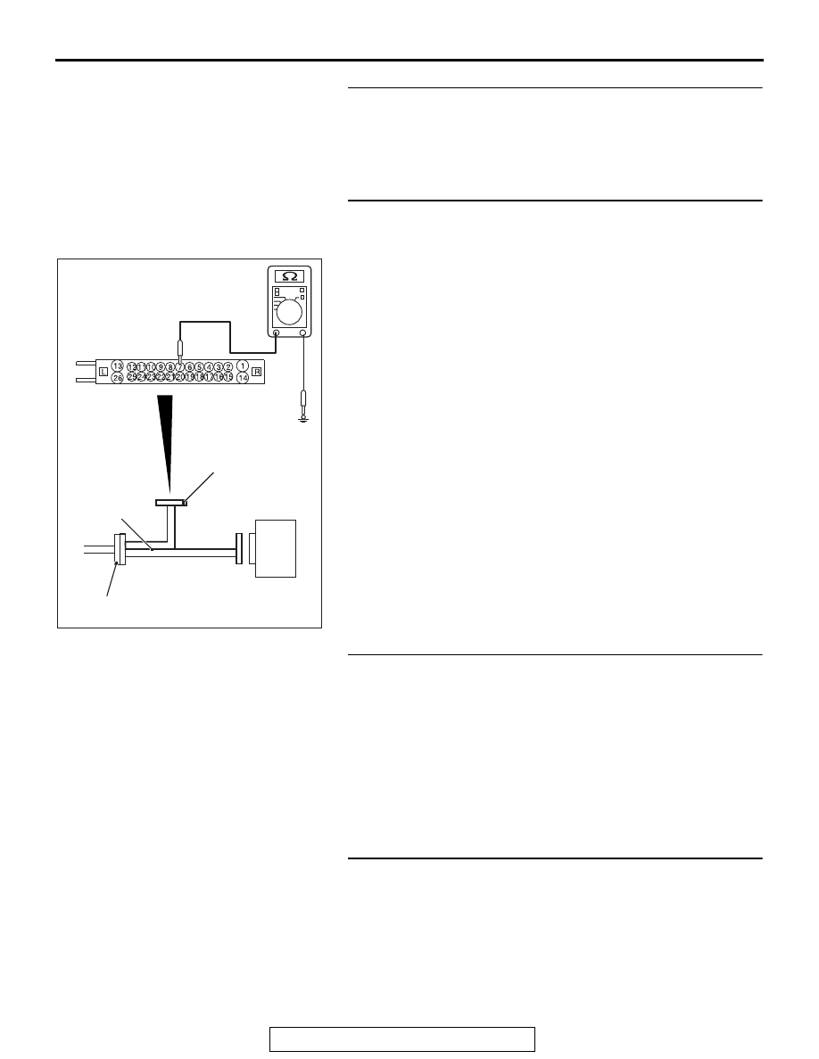
STEP 10. Resistance measurement at A-01 ABS-ECU 
connector
(1) Disconnect the C-317 ETACS-ECU connector.
(2) Disconnect the ABS-ECU connector, connect special tool 

ABS check harness (MB991974) to the harness-side 
connector, and then measure the resistance at the special 
tool connector side.
NOTE: Do not connect the special tool ABS check harness 
(MB991974) to ABS-ECU.

(3) Measure the resistance between the terminal No.7 and the 

body ground.

OK: No continuity

Q: Is the check result normal?

YES : Replace the fuse No.12. Then go to Step 20.
NO :  The short circuit may be present in the power supply 

circuit. Repair the wiring harness between the A-01 
ABS-ECU connector terminal No.7 and the C-317 
ETACS-ECU connector terminal No.5, and then 
replace the fuse No.12. Then go to Step 20.

STEP 11. Measure the voltage at the C-309 ETACS-ECU 
connector.
(1) Disconnect the connector, and measure at the wiring 

harness-side connector.

(2) Measure the voltage between the terminal No.1 and the 

body ground.

OK: Approximately system voltage

Q: Is the check result normal?

YES : Go to Step 14.
NO :  Go to Step 12.

STEP 12. Fusible link check: Check the fusible link No.34.
Q: Is the check result normal?

YES : Go to Step 14.
NO :  Go to Step 13.

AC606869 HN

ABS-ECU

MB991974

Check harness

A-01 ABS-ECU
harness connector

ABS DIAGNOSIS

TSB Revision

ANTI-LOCK BRAKING SYSTEM (ABS)

35B-130

STEP 13. Resistance measurement at C-309 ETACS-ECU 
connector
(1) Removal the fusible link No.34.
(2) Disconnect the C-309 ETACS-ECU connector, and then 

measure the resistance at the harness connector side.

(3) Measure the resistance between the terminal No.1 and the 

body ground.

OK: No continuity

Q: Is the check result normal?

YES : Replace the fusible link No.34. Then go to Step 20.
NO :  The short circuit may be present in the power supply 

circuit. Repair the wiring harness between the C-309 
ETACS-ECU connector terminal No.1 and the fusible 
link No.34, and then replace the fusible link No.34. 
Then go to Step 20.

STEP 14. Resistance measurement at fusible link No.34 
and C-309 ETACS-ECU connector
(1) Disconnect the C-309 ETACS-ECU connector and fusible 

link No.34, and then measure the resistance at the harness 
connector side.

(2) Measure the resistance between the fusible link No.34 and 

C-309 ETACS-ECU connector terminal No.1.

OK: Continuity exists (2 

Ω or less)

Q: Is the check result normal?

YES : Go to Step 15.
NO :  The open circuit may be present in the power supply 

circuit. Repair the wiring harness between the fusible 
link No.34 and C-309 ETACS-ECU connector terminal 
No.1. Then go to Step 20.

ABS DIAGNOSIS

TSB Revision

ANTI-LOCK BRAKING SYSTEM (ABS)

35B-131

STEP 15. Resistance measurement at A-01 ABS-ECU 
connector
(1) Disconnect the C-317 ETACS-ECU connector.
(2) Disconnect the A-01 ABS-ECU connector, connect special 

tool ABS check harness (MB991974) to the harness-side 
connector, and then measure the resistance at the special 
tool connector side.
NOTE: Do not connect the special tool ABS check harness 
(MB991974) to ABS-ECU.

(3) Measure the resistance between the A-01 ABS-ECU 

connector terminal No.7 and the C-317 ETACS-ECU 
connector terminal No.5.

OK: Continuity exists (2 

Ω or less)

Q: Is the check result normal?

YES : Go to Step 16.
NO :  The open circuit may be present in the power supply 

circuit. Repair the wiring harness between the A-01 
ABS-ECU connector terminal No.7 and the C-317 
ETACS-ECU connector terminal No.5. Then go to 
Step 20.

STEP 16. Measure the voltage at the C-317 ETACS-ECU 
connector.
(1) Measure by backprobing without disconnecting the 

connector.

(2) Turn the ignition switch to the ON position.
(3) Measure the voltage between the terminal No.6 and the 

body ground.

OK: Approximately system voltage

Q: Is the check result normal?

YES : Go to Step 18.
NO :  Go to Step 17.

AC606869 HO

ABS-ECU

MB991974

Check harness

A-01 ABS-ECU
harness connector

Connector: C-317
(harness side)

ABS DIAGNOSIS

TSB Revision

ANTI-LOCK BRAKING SYSTEM (ABS)

35B-132

STEP 17. Resistance measurement at C-317 ETACS-ECU 
connector and the C-210 ignition switch connector
(1) Disconnect the C-317 ETACS-ECU connector and C-210 

ignition switch connector, and then measure the resistance 
at the harness connector side.

(2) Measure the resistance between the C-317 ETACS-ECU 

connector terminal No.6 and C-210 ignition switch 
connector terminal No.2.

OK: Continuity exists (2 

Ω or less)

Q: Is the check result normal?

YES : Go to Step 18.
NO :  The open circuit may be present in the power supply 

circuit. Repair the wiring harness between the C-317 
ETACS-ECU connector terminal No.6 and C-210 
ignition switch connector terminal No.2. Then go to 
Step 20.

STEP 18. Check whether the DTC is reset.
(1) Erase the DTC.
(2) Drive the vehicle at 12mph (20 km/h) or higher.
Q: Is the DTC C2100 set?

YES : Replace the ETACS-ECU (Refer to GROUP 54A 

− 

ETACS-ECU 

P.54A-825

). Then go to Step 19.

NO :  Intermittent malfunction (Refer to GROUP 00 

− How 

to Use Troubleshooting/How to Cope with Intermittent 
Malfunctions 

P.00-15

).

STEP 19. Check whether the DTC is reset.
(1) Erase the DTC.
(2) Drive the vehicle at 12mph (20 km/h) or higher.
Q: Is the DTC C2100 set?

YES : Replace the hydraulic unit (integrated with ABS-ECU) 

(Refer to 

P.35B-188

). Then go to Step 20.

NO :  Intermittent malfunction (Refer to GROUP 00 

− How 

to Use Troubleshooting/How to Cope with Intermittent 
Malfunctions 

P.00-15

).

STEP 20. Check whether the DTC is reset.
(1) Erase the DTC.
(2) Drive the vehicle at 12mph (20 km/h) or higher.
Q: Is the DTC C2100 set?

YES : Return to Step 1.
NO :  The procedure is complete.


Content   ..  375  376  377  378   ..