Mitsubishi Outlander GS45X. Manual - part 375


  Index      Mitsubishi     Mitsubishi Outlander GS45X - service repair manual


Search            


Content   ..  373  374  375  376   ..


Mitsubishi Outlander GS45X. Manual - part 375


ABS DIAGNOSIS

TSB Revision

ANTI-LOCK BRAKING SYSTEM (ABS)

35B-121

DTC C1000 Abnormality in stop light switch circuit

CAUTION

• If there is any problem in the CAN bus lines, an incor-

rect DTC may be set. Prior to this diagnosis, diagnose 
the CAN bus lines (Refer to GROUP 54C 

 CAN Bus 

Line Diagnostic Flow 

P.54C-10

).

• Whenever ECU is replaced, ensure that the CAN bus 

lines are normal.

.

OPERATION

ETACS-ECU sends the ON signal generated when the brake 
pedal is depressed and OFF signal generated when it is 
released to ABS-ECU via the CAN bus lines.

.

ETACS-
ECU

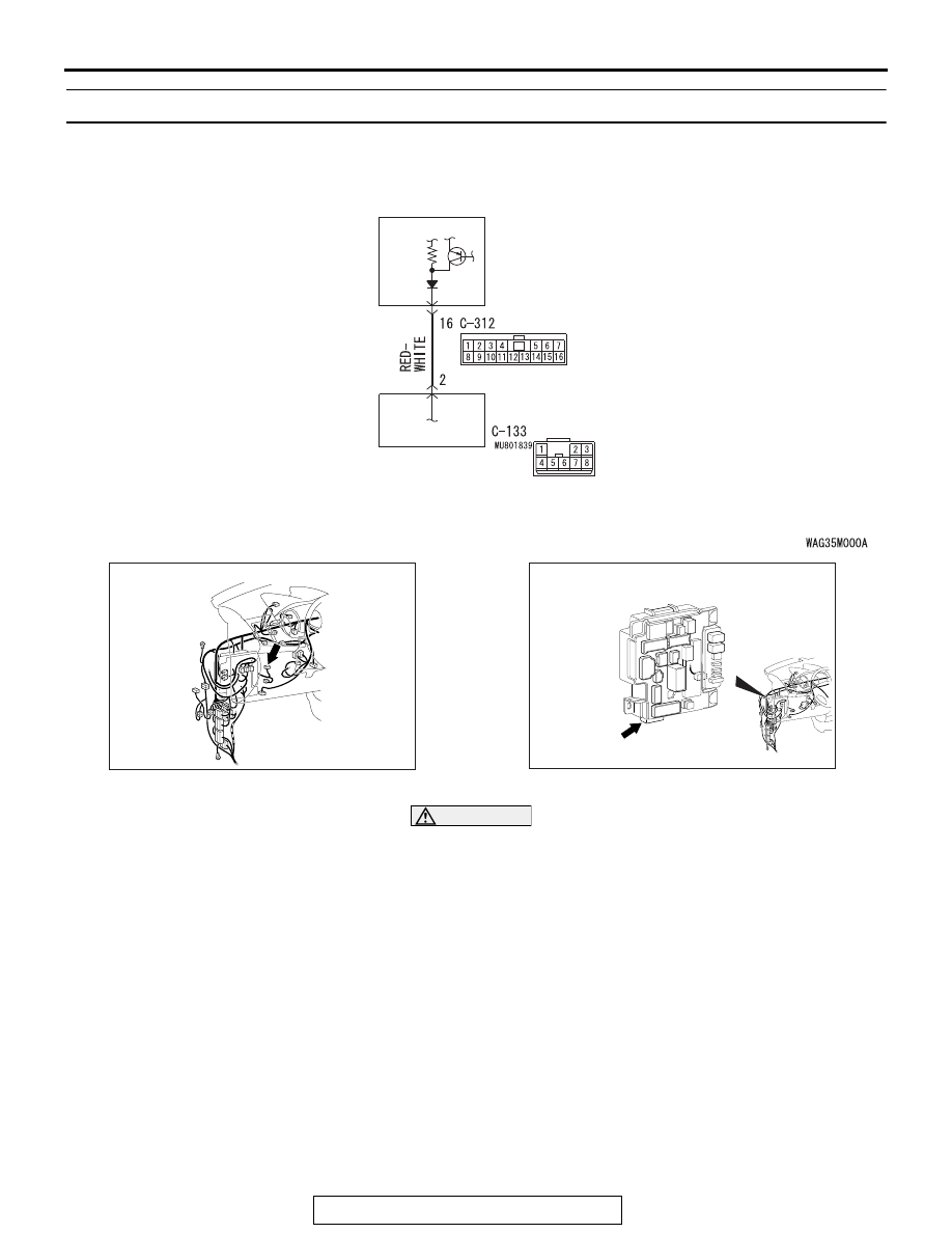
Stop Light Relay Circuit

STOP LIGHT 
RELAY

AC901075BD

Connector: C-133

AC702828AE

Connector: C-312

ABS DIAGNOSIS

TSB Revision

ANTI-LOCK BRAKING SYSTEM (ABS)

35B-122

DTC SET CONDITIONS

This DTC is set in the following case.

• When the vehicle has run for a long time with the stoplight 

switch turned ON.

• When the OFF status of the stoplight switch does not match 

the vehicle attitude

.

PROBABLE CAUSES

• Malfunction of the stoplight relay

• Damaged wiring harness and connectors

• ETACS-ECU malfunction

• ABC-ECU malfunction

DIAGNOSIS

Required Special Tools:

• MB991958 Scan Tool (M.U.T.-III Sub Assembly)

• MB991824: Vehicle Communication Interface (V.C.I.)

• MB991827 M.U.T.-III USB Cable

• MB991910 M.U.T.-III Main Harness A

STEP 1. Check that the stoplight of the rear combination 
light illuminates normally.
Q: Is the check result normal?

YES : Go to Step 2.
NO :  Diagnose the rear combination light (Refer to GROUP 

54A 

− Rear Combination light/Trouble Symptom 

Chart 

P.54A-243

). On completion, go to Step 2 .

STEP 2. Using scan tool MB991958, diagnose the CAN bus 
lines.
Use M.U.T.-III to diagnose the CAN bus lines.
Q: Is the check result normal?

YES : Go to Step 4.
NO :  Repair the CAN bus lines (Refer to GROUP 54C 

− 

CAN Bus Diagnostics Table 

P.54C-17

). On 

completion, go to Step 3.

STEP 3. DTC recheck after resetting CAN bus lines
Q: Is DTC C1000 set?

YES : Go to Step 4.
NO :  The procedure is complete.

STEP 4. Battery check
Refer to GROUP 54A 

− Battery Test 

P.54A-9

.

Q: Is the battery in good condition?

YES : Go to Step 5.
NO :  Charge or replace the battery, and go to Step 10.

ABS DIAGNOSIS

TSB Revision

ANTI-LOCK BRAKING SYSTEM (ABS)

35B-123

STEP 5. Connector check: C-312 ETACS-ECU connector
Q: Is the check result normal?

YES : Go to Step 6.
NO :  Repair the damaged connector.

STEP 6. Measure the voltage at the C-312 ETACS-ECU 
connector.
(1) Measure by backprobing without disconnecting the 

ETACS-ECU connector and stoplight switch connector.

(2) Disconnecting the C-133 stoplight relay connector.
(3) Measure the voltage between the C-312 ETACS-ECU 

connector terminal No.16 and the body ground.

OK:

When the brake pedal is released: Approximately 

0 V 

 5 V (pulse)

When the brake pedal is depressed: Approxi-

mately system voltage

Q: Is the check result normal?

YES : Go to Step 9.
NO :  Go to Step 7.

STEP 7. Connector check: C-312 ETACS-ECU connector
Q: Is the check result normal?

YES : Go to Step 8.
NO :  Repair the damaged connector.

STEP 8. Check the wiring harness between C-312 
ETACS-ECU connector terminal No.16 and C-133 stoplight 
relay connector terminal No.2

• Check the signal line for open circuit.

Q: Is the check result normal?

YES : Go to Step 9.
NO :  Replace the wiring harness.

STEP 9. Diagnostic trouble code recheck
Erase the DTC.
Q: Is diagnostic trouble code No.C1000 set?

YES : Replace the hydraulic unit (integrated with ABC-ECU) 

(Refer to 

P.35C-282

). Then go to Step 10.

NO :  Intermittent malfunction (Refer to GROUP 00 

− How 

to Use Troubleshooting/How to Cope with Intermittent 
Malfunctions 

P.00-15

).

STEP 10. Diagnostic trouble code recheck
Erase the DTC.
Q: Is diagnostic trouble code No.C1000 set?

YES : Return to Step 1.
NO :  The procedure is complete.

ABS DIAGNOSIS

TSB Revision

ANTI-LOCK BRAKING SYSTEM (ABS)

35B-124

DTC C2200 Abnormality in ABS-ECU

CAUTION

• If there is any problem in the CAN bus lines, an incor-

rect DTC may be set. Prior to this diagnosis, diagnose 
the CAN bus lines (Refer to GROUP 54C 

 CAN Bus 

Line Diagnostic Flow 

P.54C-10

).

• Whenever ECU is replaced, ensure that the CAN bus 

lines are normal.

.

OPERATION

ABS-ECU controls ABS by calculating the data sent from the 
wheel speed sensor and the G sensor.

.

DTC SET CONDITIONS

This DTC is set when ABS-ECU has malfunction.

.

PROBABLE CAUSES

ABS-ECU malfunction

DIAGNOSIS

Required Special Tools:

• MB991958: Scan Tool (M.U.T.-III Sub Assembly)

• MB991824: Vehicle Communication Interface (V.C.I.)

• MB991827: M.U.T.-III USB Cable

• MB991910: M.U.T.-III Main Harness A

STEP 1. Using scan tool MB991958, diagnose the CAN bus 
line.
Use scan tool MB991958 to diagnose the CAN bus lines.
Q: Is the check result normal?

YES : Go to Step 2.
NO :  Repair the CAN bus lines (Refer to GROUP 54C 

− 

CAN Bus Diagnostics Table 

P.54C-17

). On 

completion, go to Step 2.

STEP 2. DTC recheck after resetting CAN bus lines
Erase the DTC.
Q: Is the DTC C2200 set?

YES : Replace the hydraulic unit (integrated with ABS-ECU) 

(Refer to 

P.35B-188

). Then go to Step 3.

NO :  Intermittent malfunction (Refer to GROUP 00 

− How 

to Use Troubleshooting/How to Cope with Intermittent 
Malfunctions 

P.00-15

).

STEP 3. DTC recheck after resetting CAN bus lines
Erase the DTC.
Q: Is the DTC C2200 set?

YES : Return to Step 1.
NO :  This diagnosis is complete.


Content   ..  373  374  375  376   ..