Mitsubishi Outlander GS45X. Manual - part 350


  Index      Mitsubishi     Mitsubishi Outlander GS45X - service repair manual


Search            


Content   ..  348  349  350  351   ..


Mitsubishi Outlander GS45X. Manual - part 350


ABS DIAGNOSIS

TSB Revision

ANTI-LOCK BRAKING SYSTEM (ABS)

35B-21

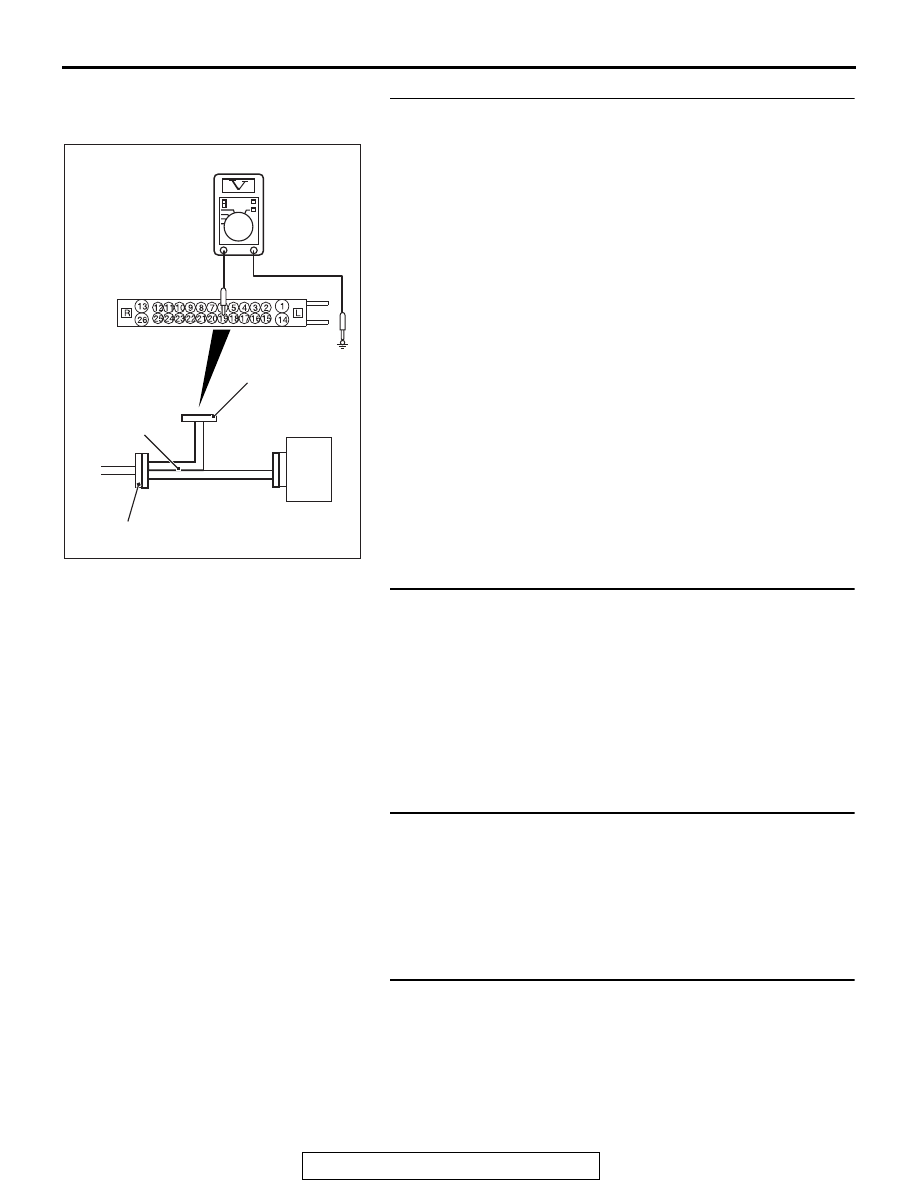
STEP 8. Voltage measurement at the A-01 ABS-ECU 
connector
(1) Disconnect the ABS-ECU connector, connect special tool 

ABS check harness (MB991974) to the ABS-ECU-side 
connector and harness-side connector, and then measure 
the voltage at the special tool connector side.

(2) Turn the ignition switch to the ON position.
(3) Measure the voltage between the front wheel speed sensor 

<LH> power supply terminal (signal terminal) No.18 and 
body ground, and between the ground terminal No.19 and 
body ground.

OK:

Terminal No.18 and body ground: Approximately 

system voltage

Terminal No.19 and body ground: 1 volt or less

Q: Is the check result normal?

YES : Go to Step 9.
NO :  Go to Step 11.

STEP 9. Wiring harness check between A-01 ABS-ECU 
connector terminal No.18 and A-11 front wheel speed 
sensor <LH> connector terminal No.1, and between A-01 
ABS-ECU connector terminal No.19 and A-11 front wheel 
speed sensor <LH> connector terminal No.2.

• Check for open circuit in front wheel speed sensor <LH> cir-

cuit

Q: Is the check result normal?

YES : Go to Step 10.
NO :  Repair the wiring harness. Then go to Step 13.

STEP 10. Check for wheel speed sensor <FL> as a single 
unit
Refer to 

P.35B-193

.

Q: Is the check result normal?

YES : Go to Step 11.
NO :  Replace the wheel speed sensor <FL> (Refer to 

P.35B-189

). Then go to Step 13.

STEP 11. Connector check: A-01 ABS-ECU connector, A-11 
front wheel speed sensor <LH> connector
Q: Is the check result normal?

YES : Go to Step 12.
NO :  Repair the defective connector. Then go to Step 13.

AC611138 AF

ABS-ECU

MB991974

A-01 ABS-ECU 
harness connector

Check harness

ABS DIAGNOSIS

TSB Revision

ANTI-LOCK BRAKING SYSTEM (ABS)

35B-22

STEP 12. Check whether the DTC is reset.
(1) Erase the DTC.
(2) Drive the vehicle at 12mph (20 km/h) or higher.

NOTE: The ABS warning light does not turn OFF in some 
cases unless the vehicle runs at 12mph (20 km/h) or higher.

Q: Is DTC C100A set?

YES : Replace the hydraulic unit (integrated with ABS-ECU) 

(Refer to 

P.35B-188

). Then go to Step 13.

NO :  Intermittent malfunction (Refer to GROUP 00 

− How 

to Use Troubleshooting/How to Cope with Intermittent 
Malfunctions 

P.00-15

).

STEP 13. Check whether the DTC is reset.
(1) Erase the DTC.
(2) Drive the vehicle at 12mph (20 km/h) or higher.

NOTE: The ABS warning light does not turn OFF in some 
cases unless the vehicle runs at 12mph (20 km/h) or higher.

Q: Is DTC C100A set?

YES : Return to Step 1.
NO :  The procedure is complete.

DTC C1015: Abnormality in FR wheel speed sensor circuit

AC705204

Wheel Speed Sensor Circuit

ABS-ECU

(LH)

(LH)

(RH)

(RH)

REAR WHEEL SPEED SENSOR

FRONT WHEEL SPEED SENSOR

AB

ABS DIAGNOSIS

TSB Revision

ANTI-LOCK BRAKING SYSTEM (ABS)

35B-23

CAUTION

If there is any problem in the CAN bus lines, an incorrect 
DTC may be set. Prior to this diagnosis, diagnose the CAN 
bus lines (Refer to GROUP 54C 

 CAN Bus Line Diagnostic 

Flow 

P.54C-10

).

.

CIRCUIT OPERATION

• The wheel speed sensor is a type of pulse generator. It con-

sists of encoders (a plate on which north and south pole 
sides of the magnets are arranged alternately) for detecting 
the wheel speed which rotates at the same speed of the 
wheels and wheel speed sensors. This sensor outputs fre-
quency pulse signals in proportion to the wheel speed.

• The pulse signals, which the wheel speed sensor creates, 

are sent to ABS-ECU. ABS-ECU uses the frequency of the 
pulse signals to determine the wheel speed.

.

DTC SET CONDITIONS

ABS-ECU monitors the voltage fluctuation in each wheel speed 
sensor circuit. If ABS-ECU detects the open or short circuit in 
the circuit, it will set a DTC.

.

PROBABLE CAUSES

Current trouble

• Damaged wiring harness and connectors

• Noise interference

• Malfunction of wheel speed sensor

• ABS-ECU malfunction

Past trouble

• Carry out diagnosis with particular emphasis on wiring har-

ness and connector failures between ABS-ECU and the 
wheel speed sensor. For diagnosis procedures, refer to 
How to treat past trouble (GROUP 00 

− How to Use Trou-

bleshooting/How to Treat Past Trouble 

P.00-17

).

AC901112

Connectors: A-01, A-59

A-01 (B)

AL

A-59 (B)

ABS DIAGNOSIS

TSB Revision

ANTI-LOCK BRAKING SYSTEM (ABS)

35B-24

DIAGNOSIS

Required Special Tools:

• MB991958: Scan Tool (M.U.T.-III Sub Assembly)

• MB991824: Vehicle Communication Interface (V.C.I.)

• MB991827: M.U.T.-III USB Cable

• MB991910: M.U.T.-III Main Harness A

• MB991974: ABS check harness

STEP 1. Using scan tool MB991958, diagnose the CAN bus 
line.
Use scan tool to diagnose the CAN bus lines.
Q: Is the check result normal?

YES : Go to Step 3.
NO :  Repair the CAN bus lines (Refer to GROUP 54C 

− 

CAN Bus Diagnostics Table 

P.54C-10

). On 

completion, go to Step 2.

STEP 2. DTC recheck after resetting CAN bus lines
Q: Is the DTC C1015 set?

YES : Go to Step 3.
NO :  The procedure is complete.

STEP 3. Scan tool data list
Check the following data list (Refer to 

P.35B-179

).

• Item No.02: FR wheel speed sensor

Q: Is the check result normal?

YES : Go to Step 12.
NO :  Go to Step 4.


Content   ..  348  349  350  351   ..