Mitsubishi Outlander GS45X. Manual - part 226
ENGINE AND TRANSAXLE <3.0L ENGINE>
TSB Revision
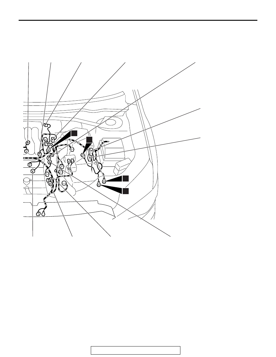
CONFIGURATION DIAGRAMS
80A-15
AC900426AB
B-05
B-06
B-07
B-08
B-09
B-10
B-11
B-12
B-13
B-14
B-15
11
13
14
3
B-13
(4-GR)
Left bank heated oxygen sensor
(Rear)
B-14
(4-B)
Left bank heated oxygen sensor
(Front)
B-15
(3-B)
No.6 ignition coil
B-16
(1)
Engine oil pressure switch
B-17
(1-B)
A/C compressor assembly
B-18
(3-B)
No.4 ignition coil
B-19
(3-B)
No.2 ignition coil
B-20
(2-B)
Knock sensor 2
B-21
(10-B)
Control wiring harness and injector
wiring harness combination
B-28
(2-GR)
Electronic control coupling solenoid
(Front) <S-AWC>