Mitsubishi Outlander GS45X. Manual - part 213


  Index      Mitsubishi     Mitsubishi Outlander GS45X - service repair manual


Search            


Content   ..  211  212  213  214   ..


Mitsubishi Outlander GS45X. Manual - part 213


THEFT ALARM

TSB Revision

CHASSIS ELECTRICAL

54A-849

DTC No.U1540 Theft alarm SNSR. LIN checksum

CAUTION

Before replacing the ECU or sensor, ensure that the power supply circuit, the ground circuit and the 
communication circuit are normal.

.

JUDGMENT CRITERIA

The ETACS-ECU will set diagnostic trouble code No. 
U1540 when abnormal signals are received from the 
theft alarm sensor.

.

PROBABLE CAUSES

Faulty theft alarm sensor

DIAGNOSIS

Required Special Tools:

• MB991958: Scan Tool (M.U.T.-III Sub Assembly)

• MB991824: Vehicle Communication Interface (V.C.I.)

• MB991827: M.U.T.-III USB Cable

• MB991910: M.U.T.-III Main Harness A (Vehicles with 

CAN communication system)

Using scan tool MB991958, read the ETACS-ECU 
diagnostic trouble code. 
Check again if the diagnostic trouble code is set to the 
ETACS-ECU.

CAUTION

To prevent damage to scan tool MB991958, always turn the 
ignition switch to the "LOCK" (OFF) position before con-
necting or disconnecting scan tool MB991958.
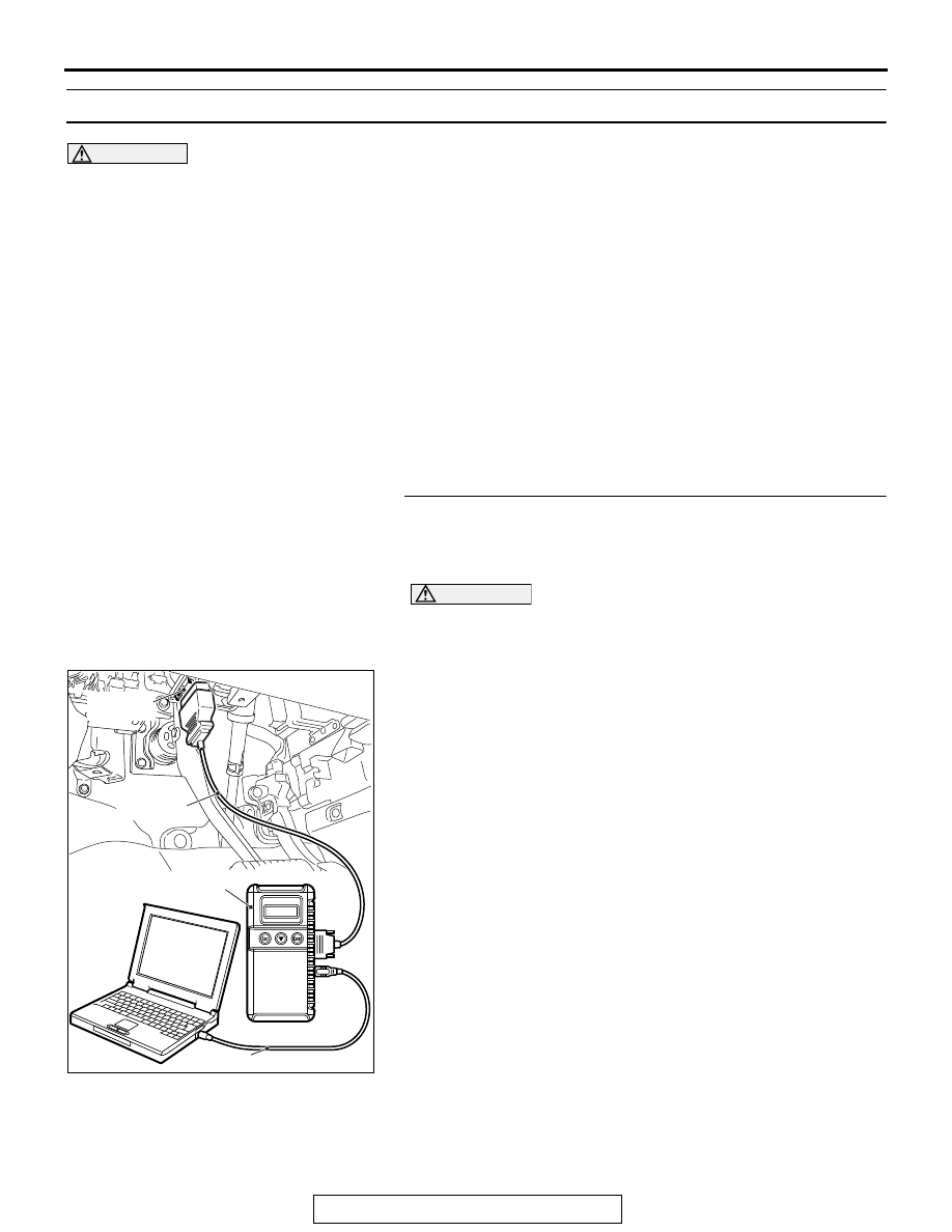
Connect scan tool MB991958. Refer to "How to connect scan 
tool (M.U.T.-III) 

P.54A-839

."

(1) Erase the DTC.
(2) Turn the ignition switch from "LOCK" (OFF) position to "ON" 

position.

(3) Check if DTC is set.
Q: Is the DTC set?

YES : Replace the theft alarm sensor.
NO :  A poor connection, open circuit, or other intermittent 

malfunctions in the LIN bus lines between the theft 
alarm sensor and the ETACS-ECU (Refer to GROUP 
00 

− How to Cope with Intermittent Malfunction 

P.00-15

).

ZC501967

AC404789

AC702802

MB991824

MB991827

MB991910

Data link

connector

AB

THEFT ALARM

TSB Revision

CHASSIS ELECTRICAL

54A-850

TROUBLE SYMPTOM CHART

M1547001500839

Trouble symptom

Inspection 
Procedure 
No.

Reference 
page

The theft-alarm is not armed (the theft-alarm indicator does not illuminate).

1

P.54A-851

The interior alarm does not work normally while the theft-alarm is triggered.

2

P.54A-857

Theft-alarm horn does not sound while the theft-alarm system is triggered.

3

P.54A-859

Horns do not sound while the theft-alarm system is triggered.

4

P.54A-864

The activated theft-alarm siren sounds even though no faulty operation is 
made.<Vehicles with theft alarm sensor>

5

P.54A-870

Security alarm siren does not sound. <Vehicles with theft alarm sensor>

6

P.54A-873

THEFT ALARM

TSB Revision

CHASSIS ELECTRICAL

54A-851

SYMPTOM PROCEDURES

Inspection Procedure 1: The theft-alarm is not armed (the theft-alarm indicator does not illuminate).

CAUTION

Before replacing the ECU, ensure that the power supply circuit, the ground circuit and the communi-
cation circuit are normal.

.

Theft-alarm Indicator Circuit

ETACS-
ECU

RELAY
BOX

FUSIBLE
LINK

36

CENTER
PANEL
UNIT

ENGINE
COMPARTMENT

AC703148 AD

Connector: C-104

C-104

ACA02655AB

Connector: C-307, C-317

C-307 (B)

C-317

THEFT ALARM

TSB Revision

CHASSIS ELECTRICAL

54A-852

TECHNICAL DESCRIPTION (COMMENT)

If this function does not work normally, the input sig-
nal circuits to the components below, the theft-alarm 
indicator, the ETACS-ECU or the CAN bus line may 
have a problem.

• Keyless entry transmitter

• Key reminder switch

• Ignition switch (ACC)

• Hood latch switch

• Door switches

• Liftgate latch switch

.

TROUBLESHOOTING HINTS

• CAN bus line may be defective

• Theft-alarm indicator may be defective

• Keyless entry transmitter may be defective

• The key reminder switch may be defective

• Door switch may be defective

• Liftgate latch switch may be defective

• Hood latch switch may be defective

• The KOS-ECU may be defective

• The WCM may be defective

• The ETACS-ECU may be defective

• The wiring harness or connectors may have 

loose, corroded, or damaged terminals, or termi-
nals pushed back in the connector

DIAGNOSIS

Required Special Tools:

• MB992006: Extra fine probe

• MB991223: Harness set

• MB991958: Scan Tool (M.U.T.-III Sub Assembly)

• MB991824: Vehicle Communication Interface (V.C.I.)

• MB991827: M.U.T.-III USB Cable

• MB991910: M.U.T.-III Main Harness A (Vehicles with 

CAN communication system)

STEP 1. Using scan tool MB991958, diagnose the CAN bus 
line.

CAUTION

To prevent damage to scan tool MB991958, always turn the 
ignition switch to the "LOCK" (OFF) position before con-
necting or disconnecting scan tool MB991958.
(1) Connect scan tool MB991958. Refer to "How to connect the 

scan tool (M.U.T.-III) 

P.54A-839

."

(2) Turn the ignition switch to the "ON" position.
(3) Diagnose the CAN bus line.
(4) Turn the ignition switch to the "LOCK" (OFF) position.
Q: Is the CAN bus line found to be normal?

YES : Go to Step 2.
NO :  Repair the CAN bus line (Refer to GROUP 54C, 

Diagnosis 

P.54C-17

).

ZC501967

AC404789

AC702802

MB991824

MB991827

MB991910

Data link

connector

AB


Content   ..  211  212  213  214   ..