Mitsubishi Outlander GS45X. Manual - part 1607


  Index      Mitsubishi     Mitsubishi Outlander GS45X - service repair manual


Search            


Content   ..  1605  1606  1607  1608   ..


Mitsubishi Outlander GS45X. Manual - part 1607


EMISSION CONTROL <MFI>

TSB Revision

ENGINE AND EMISSION CONTROL

17-77

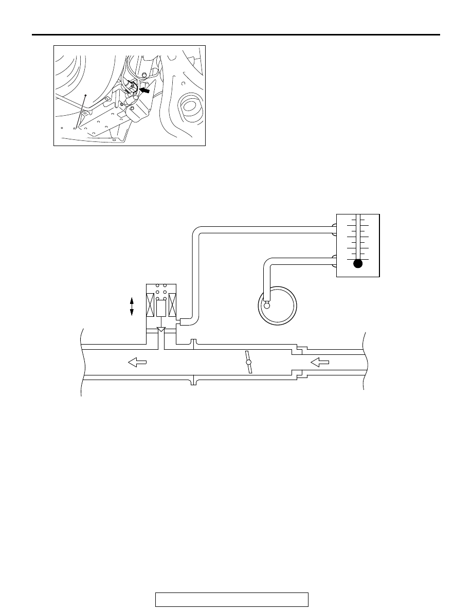
PURGE CONTROL SYSTEM CHECK 


(PURGE FLOW CHECK)

M1173001401593

Required Special Tool:
MB995061: Purge Flow Indicator
1. Disconnect the purge hose from the evaporative emission 

(EVAP) purge solenoid, and connect special tool MB995061 
between the EVAP purge solenoid and the purge hose.

2. Before inspection, set the vehicle in the following conditions:

• Engine coolant temperature: 80 − 95°C (176 − 203°F)

• Lights, electric cooling fan and accessories: OFF

• Transaxle: P range

NOTE: Vehicles for Canada, the headlight, taillight, etc. 
remain lit even when the lighting switch is in "OFF" position 
but this is no problem for checks.

AK700061

AB

Spare tire

Evaporative emission ventilation solenoid

AK604168 AB

Intake manifold

Throttle body

From 
aircleaner

To 
combustion 
chamber

OFF

ON

Evaporative 
emission 
purge solenoid 
(ON: Open)

Evaporative 
emission 
canister

Purge flow 
indicator 
(MB995061)

Purge hose

EMISSION CONTROL <MFI>

TSB Revision

ENGINE AND EMISSION CONTROL

17-78

3. Run the engine at idle for more than four minutes.
4. Check the purge flow volume when engine is revved 

suddenly several times.

Standard value: Momentarily 20 cm

3

/s (2.5 SCFH) or 

more.

5. If the purge flow volume is less than the standard value, 

check it again with the vacuum hose disconnected from the 
EVAP canister. If the purge flow volume is less than the 
standard value, check the vacuum port and the vacuum 
hose for clogging. Also check the EVAP purge solenoid. If 
the purge flow volume is at the standard value, replace the 
EVAP canister.

EVAPORATIVE EMISSION PURGE SOLENOID 
CHECK

M1173001701044

1. Disconnect the vacuum hose from the evaporative emission 

(EVAP) purge solenoid.

2. Disconnect the harness connector.
3. Connect a hand vacuum pump to nipple (A) of the EVAP 

purge solenoid (refer to the illustration at left).

4. As described in the chart below, check airtightness by 

applying a vacuum with voltage applied directly from the 
battery to the EVAP purge solenoid valve and without 
applying voltage.

5. Measure the resistance between the terminals of the EVAP 

purge solenoid.

Standard value: 22 

 26 Ω [at 20°C (68°F)]

6. Replace the solenoid if resistance is out of specification.

BATTERY POSITIVE 
VOLTAGE

NORMAL CONDITION

Applied

Vacuum leaks

Not applied

Vacuum maintained

AK402742AK

A

B

Battery

AK502148

EMISSION CONTROL <MFI>

TSB Revision

ENGINE AND EMISSION CONTROL

17-79

MASS AIRFLOW SENSOR CHECK

M1173050400224

.

<2.4L Engine>

To inspect these parts, refer to GROUP 13A, Multiport Fuel 
Injection (MFI) <2.4L Engine> 

− Multiport Fuel Injection (MFI) 

Diagnosis 

− Diagnostic Trouble Code Chart 

P.13A-49

.

.

<3.0L Engine>

To inspect these parts, refer to GROUP 13B, Multiport Fuel 
Injection (MFI) <3.0L Engine> 

− Multiport Fuel Injection (MFI) 

Diagnosis 

− Diagnostic Trouble Code Chart 

P.13B-50

.  

BAROMETRIC PRESSURE SENSOR CHECK

M1173008000377

.

<2.4L Engine>

To inspect the sensor, refer to GROUP 13A, Multiport Fuel 
Injection (MFI) <2.4L Engine> 

− Multiport Fuel Injection (MFI) 

Diagnosis 

− Diagnostic Trouble Code Chart 

P.13A-49

.

.

<3.0L Engine>

To inspect the sensor, refer to GROUP 13B, Multiport Fuel 
Injection (MFI) <3.0L Engine> 

− Multiport Fuel Injection (MFI) 

Diagnosis 

− Diagnostic Trouble Code Chart 

P.13B-50

ENGINE COOLANT TEMPERATURE SENSOR 
CHECK

M1173008100783

.

<2.4L Engine>

To inspect the sensor, refer to GROUP 13A, Multiport Fuel 
Injection (MFI) <2.4L Engine> 

− Multiport Fuel Injection (MFI) 

Diagnosis 

− Diagnostic Trouble Code Chart 

P.13A-49

.

.

<3.0L Engine>

To inspect the sensor, refer to GROUP 13B, Multiport Fuel 
Injection (MFI) <3.0L Engine> 

− Multiport Fuel Injection (MFI) 

Diagnosis 

− Diagnostic Trouble Code Chart 

P.13B-50

INTAKE AIR TEMPERATURE SENSOR CHECK

M1173008200423

.

<2.4L Engine>

To inspect the sensor, refer to GROUP 13A, Multiport Fuel 
Injection (MFI) <2.4L Engine> 

− Multiport Fuel Injection (MFI) 

Diagnosis 

− Diagnostic Trouble Code Chart 

P.13A-49

.

.

<3.0L Engine>

To inspect the sensor, refer to GROUP 13B, Multiport Fuel 
Injection (MFI) <3.0L Engine> 

− Multiport Fuel Injection (MFI) 

Diagnosis 

− Diagnostic Trouble Code Chart 

P.13B-50

EMISSION CONTROL <MFI>

TSB Revision

ENGINE AND EMISSION CONTROL

17-80

FUEL TANK DIFFERENTIAL PRESSURE SENSOR 
CHECK

M1173007700317

To inspect the sensor, refer to GROUP 13C, Fuel Supply 

− Fuel 

Tank 

− Fuel Tank Inspection − Fuel Tank Differential Pressure 

Sensor Check 

P.13C-27

.

EVAPORATIVE EMISSION VENTILATION 
SOLENOID CHECK

M1173007800273

Refer to Emission Control 

− Evaporative Emission Canister and 

Fuel Tank Pressure Relief Valve 

− Inspection − Evaporative 

Emission Ventilation Solenoid Check 

P.17-88

.

EXHAUST GAS RECIRCULATION (EGR) SYSTEM

GENERAL INFORMATION (EXHAUST GAS RECIRCULATION SYSTEM)

M1173005201085

The exhaust gas recirculation system (EGR) lowers 
the nitrogen oxides (NOx) emission level. When the 
air/fuel mixture combustion temperature is high, a 
large quantity of NOx is generated in the combustion 
chamber. Therefore, this system recirculates part of 
exhaust gas from the exhaust port of the cylinder 
head to the combustion chamber through the intake 
manifold to decrease the air/fuel mixture combustion 
temperature, resulting in reduction of NOx. The EGR 
flow rate is controlled by the EGR valve (Stepper 
Motor) for driveability quality.

OPERATION

When the engine coolant temperature is low, when 
the engine is at idle or when a wide open throttle 
operation is performed, the EGR valve (Stepper 
Motor) is kept closed, achieving no EGR. After warm-
ing up the engine, the EGR valve (Stepper Motor) 
can be opened by the engine control module (ECM).
The ECM monitors the EGR system and illuminates 
the Malfunction Indicator Lamp (SERVICE ENGINE 
SOON or Check Engine Lamp) to indicate that there 
is a malfunction.

SYSTEM DIAGRAM
<2.4L Engine>

AK502987AE

ECM

Mass airflow sensor

Intake air temperature sensor

Manifold absolute

pressure sensor

Engine coolant

temperature sensor

Throttle position sensor

Crankshaft position sensor

Battery

EGR valve

(stepper motor)


Content   ..  1605  1606  1607  1608   ..