Content .. 1522 1523 1524 1525 ..
Mitsubishi Outlander GS45X. Manual - part 1524
DIFFERENTIAL CARRIER ASSEMBLY
TSB Revision
REAR AXLE <AWD>
27B-45
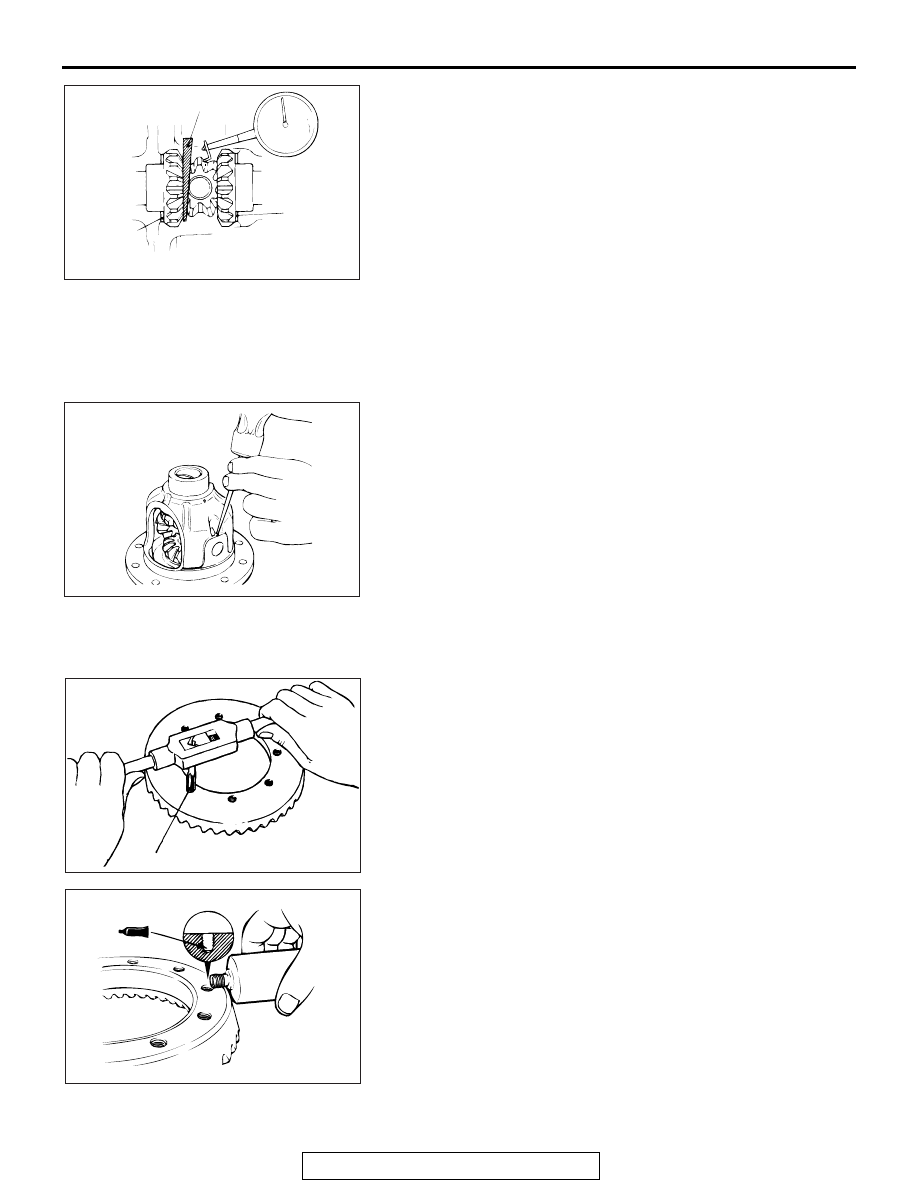
3. Drive a wooden wedge between one of the side gears and
the pinion shaft to fix the side gear.
4. Set a dial gauge (with the measuring rod extended) against
the pinion gear and measure the backlash. Repeat the same
procedure to measure the backlash at the other pinion gear.
Standard value: 0
− 0.076 mm (0 − 0.0030 inch)
Limit: 0.2 mm (0.01 inch)
5. When the backlash exceeds the limit value, adjust it by
selecting the side gear spacer.
6. When the adjustment is not possible, replace the side gear
and the pinion gear as a set.
7. After the adjustments, make sure that the backlash is within
the limit value and the differential gear rotates smoothly.
.
>>F<< LOCK PIN INSTALLATION
1. Align the lock pin holes in the pinion shaft and in the
differential case, and drive in the lock pin.
2. Use a punch to crimp two points.
.
>>G<< DRIVE GEAR INSTALLATION
1. Remove adhesive on the drive gear tightening bolts.
2. Use a tap to remove adhesive in the drive gear screw holes,
and clean the holes by blowing air.
3. Apply the specified thread locking compound in the drive
gear screw holes.
Specified adhesive: 3M
™ AAD Part No.8730, 8731 or
equivalent
4. Align the mating marks and assemble the drive gear to the
differential case.
Tightening torque: 41
± 5 N⋅m (30 ± 3 ft-lb)
.
AC703506AB
Side gear
spacer
Side gear
spacer
Wedge
AC703533 AB
AC703534AB
M8 X 1.0 (pitch)
AC703535AB