Mitsubishi Outlander GS45X. Manual - part 1502


  Index      Mitsubishi     Mitsubishi Outlander GS45X - service repair manual


Search            


Content   ..  1500  1501  1502  1503   ..


Mitsubishi Outlander GS45X. Manual - part 1502


ON-VEHICLE SERVICE

TSB Revision

FRONT AXLE

26-11

MB990925 BEARING AND OIL SEAL INSTALLER SET

ON-VEHICLE SERVICE

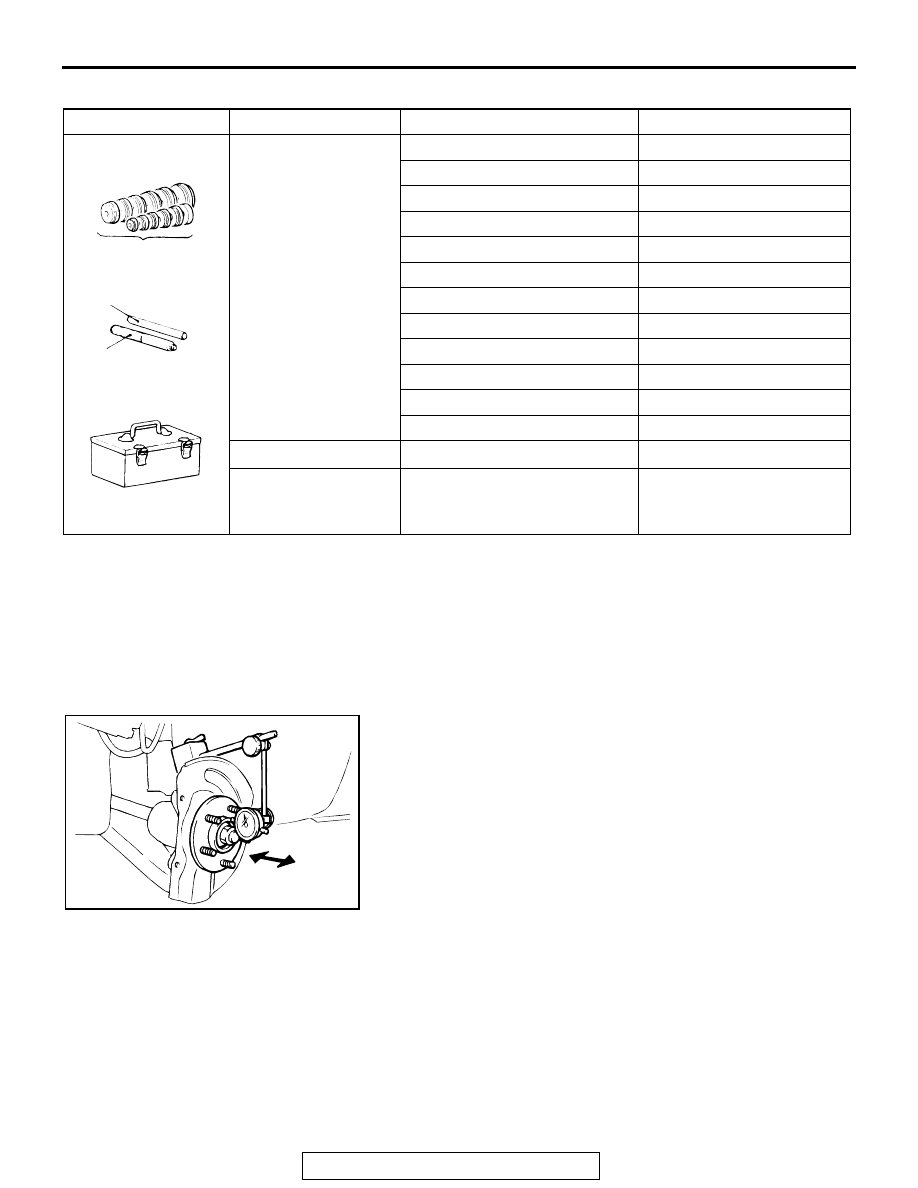
WHEEL BEARING END PLAY CHECK

M1261001100362

1. Remove the front caliper assembly and front brake disc, and 

retain the front caliper assembly with a wire and the like to 
prevent from falling (Refer to 

P.26-13

).

2. Set a dial gauge as shown in the figure. Move the hub in the 

axial direction and measure the end play.

Limit: 0.05 mm (0.002 inch)

3. If the play exceeds the limit, disassemble hub knuckle to 

check each component. If the front hub bearing is faulty, 
replace it.

4. After checking, install the front brake disc and the front 

caliper assembly (Refer to 

P.26-13

).

Tool

Type

Tool number

O D mm (in)

A

MB990926

39.0 (1.54)

MB990927

45.0 (1.77)

MB990928

49.5 (1.95)

MB990929

51.0 (2.00)

MB990930

54.0 (2.13)

MB990931

57.0 (2.24)

MB990932

61.0 (2.40)

MB990933

63.5 (2.50)

MB990934

67.5 (2.66)

MB990935

71.5 (2.81)

MB990936

75.5 (2.97)

MB990937

79.0 (3.11)

B

MB990938

C

MB990939

AC703349 AB

A

B

C

Installer bar
(Snap-in type)

Installer adapter

MB990925

Remover bar

Tool box

AC703296 AB

ON-VEHICLE SERVICE

TSB Revision

FRONT AXLE

26-12

HUB BOLT REPLACEMENT

M1261001000536

Required Special Tools:

• MB990767: Front Hub and Flange Yoke Holder

• MB991618: Hub Bolt Remover

1. Remove the front caliper assembly and front brake disc, and 

retain the front caliper assembly with a wire and the like to 
prevent from falling (Refer to 

P.26-13

).

2. Use special tool MB991618 to remove the hub bolts.

3. Install the plain washer to the new hub bolt, and install the 

bolt with a nut while holding the hub with special tool 
MB990767.

4. Install the front brake disc and the front caliper assembly 

(Refer to 

P.26-13

).

AC703297AB

MB991618

Hub bolt

AC612767AD

MB990767

Plain 
washer

FRONT AXLE HUB ASSEMBLY

TSB Revision

FRONT AXLE

26-13

FRONT AXLE HUB ASSEMBLY

REMOVAL AND INSTALLATION

M1261001701679

CAUTION

• The magnetic encoder collects metallic particles easily, because it is magnetized. Make sure that 

the magnetic encoder should not collect metallic particles. Check that there is not any trouble 
prior to reassembling it.

• When removing and installing the front wheel hub assembly, make sure that the magnetic encoder 

(integrated with the inner oil seal) does not contact with surrounding parts to avoid damage.

• When removing and installing the front wheel speed sensor, make sure that the sensor head at the 

end does not contact with surrounding parts to avoid damage.

• The parts indicated by * are the nuts with friction coefficient stabilizer. In removal, ensure there is 

no damage, clean dust and soiling from the bearing and thread surfaces, and tighten them to the 
specified torque.

Post-installation operation
• Using your fingers, press the Ball Joint Dust Cover to 

check for a crack or damage.

AC505531

N

5

7

110 ± 11 N·m
81 ± 8 ft-lb

25 ± 5 N·m
18 ± 3 ft-lb

71 ± 10 N·m
52 ± 7 ft-lb

8.5 ± 1.5 N·m
76 ±13 in-lb

100 ± 10 N·m
74 ± 7 ft-lb

AB

3

1

2

4

6

N

13 ± 2 N·m
115 ± 17 in-lb

*

*

N

39 ± 6 N·m
29 ± 4 ft-lb

144 - 176 N·m
107 - 129 ft-lb

9

8

10

11

12

14

13

*

*

Removal steps 

1.

Cotter pin

<<

A

>> >>

B

<< 2.

Driveshaft nut

>>

B

<< 3.

Washer

4.

Front wheel speed sensor

5.

Front wheel speed sensor harness 
bracket

6.

Brake hose bracket

<<

B

>>

7.

Caliper assembly

8.

Brake disk

<<

C

>> >>

A

<< 9.

Stabilizer link connection

10. Self-locking nut (lower arm ball 

joint connection)

<<

D

>>

11. Self-locking nut (tie-rod end 

connection)

Removal steps (Continued)

FRONT AXLE HUB ASSEMBLY

TSB Revision

FRONT AXLE

26-14

Required Special Tools:

• MB990242: Puller Shaft

• MB990244: Puller Ball 

• MB990767: Front Hub and Flange Yoke Holder

• MB991354: Puller Body

• MB991897 or MB992011: Ball Joint Remover

REMOVAL SERVICE POINTS

.

<<A>> DRIVESHAFT NUT REMOVAL

CAUTION

Do not apply the vehicle weight on the front wheel hub 
assembly with the driveshaft nut loosened. Otherwise, the 
wheel bearing may be broken.
Use special tool MB990767 to counter the hub as shown in the 
figure to remove the driveshaft nut.

.

<<B>> CALIPER ASSEMBLY REMOVAL

1. Remove the caliper assembly with brake hose.
2. Secure the removed caliper assembly with a wire or other 

similar material at a position where it will not interfere with 
the removal and installation of the hub knuckle assembly.

.

<<C>> STABILIZER LINK DISCONNECTION

Use a hexagon wrench to remove the stabilizer link and strut 
connection nut as shown in the figure.

.

<<

E

>>

12. Driveshaft and hub knuckle 

assembly connection

13. Hub knuckle assembly and strut 

mounting bolt and nuts

14. Hub knuckle assembly

Removal steps (Continued)

AC703300AB

MB990767

AC613526 AD

Stabilizer link

Strut assembly

Hexagon wrench

Stabilizer link and
strut connection nut


Content   ..  1500  1501  1502  1503   ..