Content .. 1483 1484 1485 1486 ..
Mitsubishi Outlander GS45X. Manual - part 1485
FRONT IMPACT SENSORS
TSB Revision
SUPPLEMENTAL RESTRAINT SYSTEM (SRS)
52B-435
2. Position the front impact sensor facing toward the front of
the vehicle as indicated by the arrow on the label, and install
it securely.
.
>>C<< POST-INSTALLATION INSPECTION
1. Reconnect the negative (
−) battery cable.
2. Turn the ignition key to "ON" position.
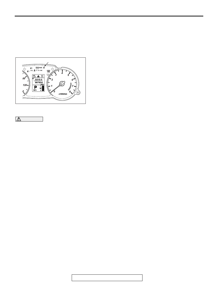
3. Does the "SRS" warning light illuminate for approximately
seven seconds, and then remain off for at least five seconds
after turning "OFF"?
4. If yes, the SRS system is functioning properly.
If not, consult page
.
INSPECTION
M1524001600716
WARNING
If a dent, crack, deformation or rust is
detected, replace with a new sensor.
NOTE: For checking of the front impact sensor other
than described below, refer to the section concerning
SRS diagnosis (Refer to
1. Check the front impact sensor and bracket for
dents, cracks or deformation.
2. Check the connector for damage, and terminals
for deformation.
3. Check that there is no bending or corrosion in the
radiator support panel.
AC901647
SRS Warning light
AB