Content .. 1470 1471 1472 1473 ..
Mitsubishi Outlander GS45X. Manual - part 1472
SRS AIR BAG DIAGNOSIS
TSB Revision
SUPPLEMENTAL RESTRAINT SYSTEM (SRS)
52B-383
DTC B1CB2: Occupant Classification-ECU Parameter Table Incompatible
DTC B2212: Occupant Classification-ECU Internal Failure
DTC B2250: Occupant Classification-ECU not Parameter Flash Required
DTC B2262: Occupant Classification-ECU Electrostatic Discharge Event Detected
CAUTION
If DTC B1CB2, B2212, B2250, B2262 is set in the
occupant classification-ECU, always diagnose
the CAN main bus lines.
.
TROUBLE JUDGMENT
The above DTC is set if an abnormality is detected in
the circuit inside the occupant classification-ECU.
.
TROUBLESHOOTING HINTS
Malfunction of the occupant classification-ECU
DIAGNOSIS
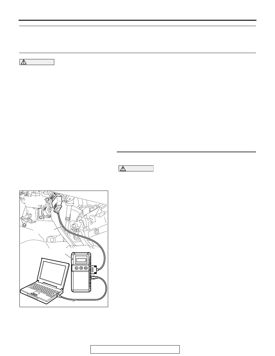
Required Special Tools:
• MB991958: Scan Tool (M.U.T.-III Sub Assembly)
• MB991824: Vehicles Communication Interface (V.C.I.)
• MB991827: M.U.T.-III USB Cable
• MB991910: M.U.T.-III Main Harness A (Vehicles with
CAN communication system)
STEP 1. Using scan tool MB991958, diagnose the CAN bus
line.
CAUTION
To prevent damage to scan tool MB991958, always turn the
ignition switch to the "LOCK" (OFF) position before con-
necting or disconnecting scan tool MB991958.
(1) Connect scan tool MB991958. Refer to "How to connect the
."
(2) Turn the ignition switch to the "ON" position.
(3) Diagnose the CAN bus line.
(4) Turn the ignition switch to the "LOCK" (OFF) position.
Q: Is the CAN bus line found to be normal?
YES : Go to Step 2.
NO : Repair the CAN bus line (Refer to GROUP 54C,
).
ZC501967
AC404789
AC701411AB
MB991824
MB991827
MB991910
Data link
connector