Mitsubishi Outlander GS45X. Manual - part 1471


  Index      Mitsubishi     Mitsubishi Outlander GS45X - service repair manual


Search            


Content   ..  1469  1470  1471  1472   ..


Mitsubishi Outlander GS45X. Manual - part 1471


SRS AIR BAG DIAGNOSIS

TSB Revision

SUPPLEMENTAL RESTRAINT SYSTEM (SRS)

52B-379

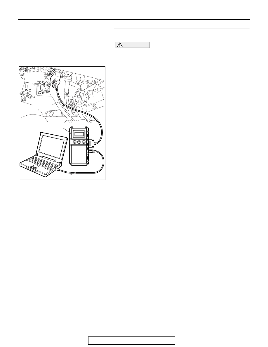
STEP 2. Using scan tool MB991958, diagnose the CAN bus 
line.

CAUTION

To prevent damage to scan tool MB991958, always turn the 
ignition switch to the "LOCK" (OFF) position before con-
necting or disconnecting scan tool MB991958.
(1) Connect scan tool MB991958. Refer to "How to connect the 

scan tool 

P.52B-28

."

(2) Turn the ignition switch to the "ON" position.
(3) Diagnose the CAN bus line.
(4) Turn the ignition switch to the "LOCK" (OFF) position.
Q: Is the CAN bus line found to be normal?

YES : Go to Step 3.
NO :  Repair the CAN bus line (Refer to GROUP 54C, 

Diagnosis 

P.54C-17

).

STEP 3. Recheck for diagnostic trouble code.
Check again if the DTC is set.
(1) Erase the DTC.
(2) Turn the ignition switch to the "ON" position.
(3) Check if the DTC is set.
(4) Turn the ignition switch to the "LOCK" (OFF) position.
Q: Is the DTC B1BBC set?

YES : Replace the passenger seat cushion frame assembly 

(Refer to GROUP 52A, Front Seat Assembly 

P.52A-19

).

NO :  There is an intermittent malfunction such as poor 

engaged connector(s) or open circuit (Refer to 
GROUP 00, How to Cope with Intermittent 
Malfunction 

P.00-15

).

ZC501967

AC404789

AC701411AB

MB991824

MB991827

MB991910

Data link 
connector

SRS AIR BAG DIAGNOSIS

TSB Revision

SUPPLEMENTAL RESTRAINT SYSTEM (SRS)

52B-380

DTC B1BBD: Occupant Classification-ECU Current Configuration table Unprogrammed

CAUTION

If DTC B1BBD is set in the occupant classifica-
tion-ECU, always diagnose the CAN main bus 
lines.

.

DTC SET CONDITIONS

The DTC is set if the check error occurs in the coding 
data of the occupant classification-ECU.

.

TROUBLESHOOTING HINTS

• Zero calibration not executed

• The occupant Classification-ECU may be defective.

DIAGNOSIS

Required Special Tools:

•  MB991958 Scan Tool (M.U.T.-III Sub Assembly)

• MB991824: Vehicle Communication Interface (V.C.I.)

• MB991827 M.U.T.-III USB Cable

• MB991910 M.U.T.-III Main Harness A (Vehicles with 

CAN communication system)

STEP 1. Using scan tool MB991958, diagnose the CAN bus 
line.

CAUTION

To prevent damage to scan tool MB991958, always turn the 
ignition switch to the "LOCK" (OFF) position before con-
necting or disconnecting scan tool MB991958.
(1) Connect scan tool MB991958. Refer to "How to connect the 

scan tool 

P.52B-28

."

(2) Turn the ignition switch to the "ON" position.
(3) Diagnose the CAN bus line.
(4) Turn the ignition switch to the "LOCK" (OFF) position.
Q: Is the CAN bus line found to be normal?

YES : Go to Step 2.
NO :  Repair the CAN bus line (Refer to GROUP 54C, 

Diagnosis 

P.54C-17

).

ZC501967

AC404789

AC701411AB

MB991824

MB991827

MB991910

Data link 
connector

SRS AIR BAG DIAGNOSIS

TSB Revision

SUPPLEMENTAL RESTRAINT SYSTEM (SRS)

52B-381

STEP 2. Recheck for diagnostic trouble code.
Check again if the DTC is set the occupant classification-ECU.
(1) Zero calibration of occupant classification -ECU 
(2) Erase the DTC.
(3) Turn the ignition switch to the "ON" position.
(4) Check if the DTC is set.
(5) Turn the ignition switch to the "LOCK" (OFF) position.
Q: Is the DTC set?

YES : Replace the passenger seat cushion frame assembly 

(Refer to GROUP 52A, Front Seat Assembly 

P.52A-17

).

NO :  There is an intermittent malfunction such as poor 

engaged connector(s) or open circuit (Refer to 
GROUP 00, How to Cope with Intermittent 
Malfunction 

P.00-15

).

DTC B1C23: Passenger Seat Weight Sensor (front: LH) Configuration Mismatch


DTC B1C24: Passenger Seat Weight Sensor (front: RH) Configuration Mismatch


DTC B1C25: Passenger Seat Weight Sensor (rear: LH) Configuration Mismatch


DTC B1C26: Passenger Seat Weight Sensor (rear: RH) Configuration Mismatch

CAUTION

If DTC B1C23, B1C24 B1C25, B1C26 is set in the 
occupant classification-ECU, always diagnose 
the CAN main bus lines.

.

DTC SET CONDITIONS

The DTC is set if the weight sensor serial No. of the 
coding data in the occupant classification-ECU does 
not match the serial No. sent from the weight sensor. 

.

TROUBLESHOOTING HINTS

• Zero calibration not executed

DIAGNOSIS

Required Special Tools:

• MB991958 Scan Tool (M.U.T.-III Sub Assembly)

• MB991824: Vehicle Communication Interface (V.C.I.)

• MB991827 M.U.T.-III USB Cable

• MB991910 M.U.T.-III Main Harness A (Vehicles with 

CAN communication system)

SRS AIR BAG DIAGNOSIS

TSB Revision

SUPPLEMENTAL RESTRAINT SYSTEM (SRS)

52B-382

STEP 1. Using scan tool MB991958, diagnose the CAN bus 
line.

CAUTION

To prevent damage to scan tool MB991958, always turn the 
ignition switch to the "LOCK" (OFF) position before con-
necting or disconnecting scan tool MB991958.
(1) Connect scan tool MB991958. Refer to "How to connect the 

scan tool 

P.52B-28

."

(2) Turn the ignition switch to the "ON" position.
(3) Diagnose the CAN bus line.
(4) Turn the ignition switch to the "LOCK" (OFF) position.
Q: Is the CAN bus line found to be normal?

YES : Go to Step 2.
NO :  Repair the CAN bus line (Refer to GROUP 54C, 

Diagnosis 

P.54C-17

).

STEP 2. Recheck for diagnostic trouble code.
Check again if the DTC is set.
(1) Erase the DTC.
(2) Turn the ignition switch to the "ON" position.
(3) Check if the DTC is set.
(4) Turn the ignition switch to the "LOCK" (OFF) position.
Q: Is the DTC set?

YES : Perform the zero calibration, and check the DTC 

again. If the DTC is set, replace the front seat cushion 
frame (RH).

NO :  There is an intermittent malfunction such as poor 

engaged connector(s) or open circuit (Refer to 
GROUP 00, How to Cope with Intermittent 
Malfunction 

P.00-15

).

ZC501967

AC404789

AC701411AB

MB991824

MB991827

MB991910

Data link 
connector


Content   ..  1469  1470  1471  1472   ..