Mitsubishi Outlander GS45X. Manual - part 1459


  Index      Mitsubishi     Mitsubishi Outlander GS45X - service repair manual


Search            


Content   ..  1457  1458  1459  1460   ..


Mitsubishi Outlander GS45X. Manual - part 1459


SRS AIR BAG DIAGNOSIS

TSB Revision

SUPPLEMENTAL RESTRAINT SYSTEM (SRS)

52B-331

STEP 5. Recheck for diagnostic trouble code.
Check again if the DTC is set.
(1) Erase the DTC.
(2) Turn the ignition switch to the "ON" position.
(3) Check if the DTC is set.
(4) Turn the ignition switch to the "LOCK" (OFF) position.
Q: Is DTC U0175 set?

YES : Replace the SRS-ECU (Refer to 

P.52B-436

). 

NO :  There is an intermittent malfunction such as poor 

engaged connector(s) or open circuit (Refer to 
GROUP 00, How to Cope with Intermittent 
Malfunction 

P.00-15

).

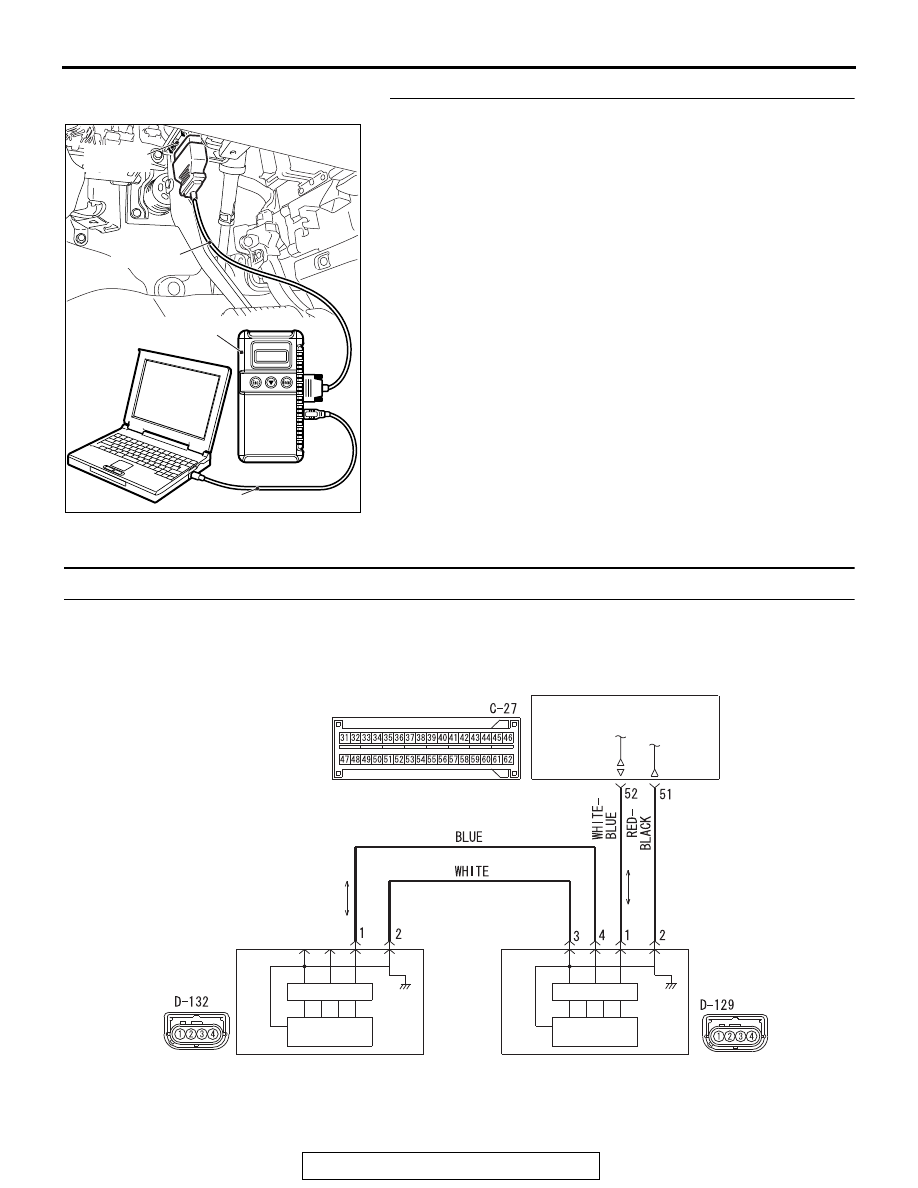
DTC U0176: Side Impact Sensor (Rear) (RH) Communication Error

ZC501967

AC404789

AC701411AB

MB991824

MB991827

MB991910

Data link 
connector

CPU

CPU

SIDE IMPACT 
SENSOR 
(FRONT: RH)

SIDE IMPACT 
SENSOR 
(REAR: RH)

ACCELERO
METER

ACCELERO
METER

AC803464

Side Impact Sensor (Front, Rear) (RH) Circuit

AC

SRS AIR BAG DIAGNOSIS

TSB Revision

SUPPLEMENTAL RESTRAINT SYSTEM (SRS)

52B-332

CAUTION

If DTC U0176 is set in the SRS-ECU, always diag-
nose the CAN main bus line.

.

CIRCUIT OPERATION

If an impact of set value or more is detected, the side 
impact sensor (rear) sends the coded acceleration 
data to SRS-ECU via side impact sensor (front). 
Based on the acceleration data, SRS-ECU deter-
mines the necessity of curtain air bag deployment, 
and then turns ON the power supply circuit to the 
inflator.

.

DTC SET CONDITIONS

These DTCs are set if communication between the 
side impact sensor (rear) (RH) and the SRS-ECU is 
not possible or faulty.

.

TROUBLESHOOTING HINTS

• Damaged wiring harnesses or connectors

• Malfunction of the side impact sensor (rear) (RH)

• Malfunction of the SRS-ECU

DIAGNOSIS

Required Special Tools:

• MB991958: Scan Tool (M.U.T.-III Sub Assembly)

• MB991824: Vehicle Communication Interface (V.C.I.)

• MB991827: M.U.T.-III USB Cable

• MB991910: M.U.T.-III Main Harness A (Vehicles with 

CAN communication system)

AC901076

C-27 (Y)

AC

Connector: C-27

AC901079

Connector: D-129

AK

D-129 (Y)

AC901080AF

Connector: D-132

D-132 (Y)

SRS AIR BAG DIAGNOSIS

TSB Revision

SUPPLEMENTAL RESTRAINT SYSTEM (SRS)

52B-333

STEP 1. Using scan tool MB991958, diagnose the CAN bus 
line.

CAUTION

To prevent damage to scan tool MB991958, always turn the 
ignition switch to the "LOCK" (OFF) position before con-
necting or disconnecting scan tool MB991958.
(1) Connect scan tool MB991958. Refer to "How to connect the 

scan tool 

P.52B-28

."

(2) Turn the ignition switch to the "ON" position.
(3) Diagnose the CAN bus line.
(4) Turn the ignition switch to the "LOCK" (OFF) position.
Q: Is the CAN bus line found to be normal?

YES : Go to Step 2.
NO :  Repair the CAN bus line (Refer to GROUP 54C, 

Diagnosis 

P.54C-17

).

STEP 2. Recheck for diagnostic trouble code.
Check again if the DTC is set.
(1) Erase the DTC.
(2) Turn the ignition switch to the "ON" position.
(3) Check if the DTC is set.
(4) Turn the ignition switch to the "LOCK" (OFF) position.
Q: Is the DTC set?

YES : Go to Step 3.
NO :  There is an intermittent malfunction such as poor 

engaged connector(s) or open circuit (Refer to 
GROUP 00, How to Cope with Intermittent 
Malfunction 

P.00-15

).

ZC501967

AC404789

AC701411AB

MB991824

MB991827

MB991910

Data link 
connector

ZC501967

AC404789

AC701411AB

MB991824

MB991827

MB991910

Data link 
connector

SRS AIR BAG DIAGNOSIS

TSB Revision

SUPPLEMENTAL RESTRAINT SYSTEM (SRS)

52B-334

STEP 3. Check for any diagnostic trouble code. (Using 
scan tool MB991958, read the diagnostic trouble code.)
Check the side impact sensor (rear) (RH).
(1) Disconnect the negative battery terminal.
(2) Alternate the side impact sensor (rear) (RH) and side 

impact sensor (rear) (LH), and then install the alternated 
sensors.

(3) Connect the negative battery terminal.
(4) Erase diagnostic trouble code from memory, and check the 

diagnostic trouble code.

Q: Is DTC U0173 set?

YES : Replace the side impact sensor (rear) (RH) with a 

new one. (Refer to 

P.52B-450

). Go to Step 5.

NO :  Go to Step 4.

STEP 4. Check the harness wires for open circuit and short 
circuit between side impact sensor (rear) (RH) connector 
D-132 (terminal No.1 and 2) and side impact sensor (front) 
(RH) connector D-129 (terminal No.4 and 3).
Q: Are the harness wires between side impact sensor 

(rear) (RH) connector D-132 (terminal No.1 and 2) and 
side impact sensor (front) (RH) connector D-129 
(terminal No.4 and 3) in good condition? 
YES : 
Go to Step 5.
NO :  Repair the harness wires between side impact sensor 

(rear) (RH) connector D-132 and side impact sensor 
(front) (RH) connector D-129.

ZC501967

AC404789

AC701411AB

MB991824

MB991827

MB991910

Data link 
connector


Content   ..  1457  1458  1459  1460   ..