Mitsubishi Outlander GS45X. Manual - part 1399


  Index      Mitsubishi     Mitsubishi Outlander GS45X - service repair manual


Search            


Content   ..  1397  1398  1399  1400   ..


Mitsubishi Outlander GS45X. Manual - part 1399


SRS AIR BAG DIAGNOSIS

TSB Revision

SUPPLEMENTAL RESTRAINT SYSTEM (SRS)

52B-91

DTC SET CONDITIONS

This DTC is set if there is abnormal resistance 
between the input terminals of the passenger’s 
(front) air bag module (squib).

.

TROUBLESHOOTING HINTS

• Open circuit in the passenger's (front) air bag 

module (squib) circuit

• Improper connector contact

• Malfunction of the SRS-ECU

DIAGNOSIS

Required Special Tools:

• MB991958: Scan Tool (M.U.T.-III Sub Assembly)

• MB991824: Vehicle Communication Interface (V.C.I.)

• MB991817: M.U.T.-III USB Cable

• MB991910: M.U.T.-III Main Harness A (Vehicles with 

CAN Communication System)

• MB991865: Dummy resister

• MB991866: Resister harness

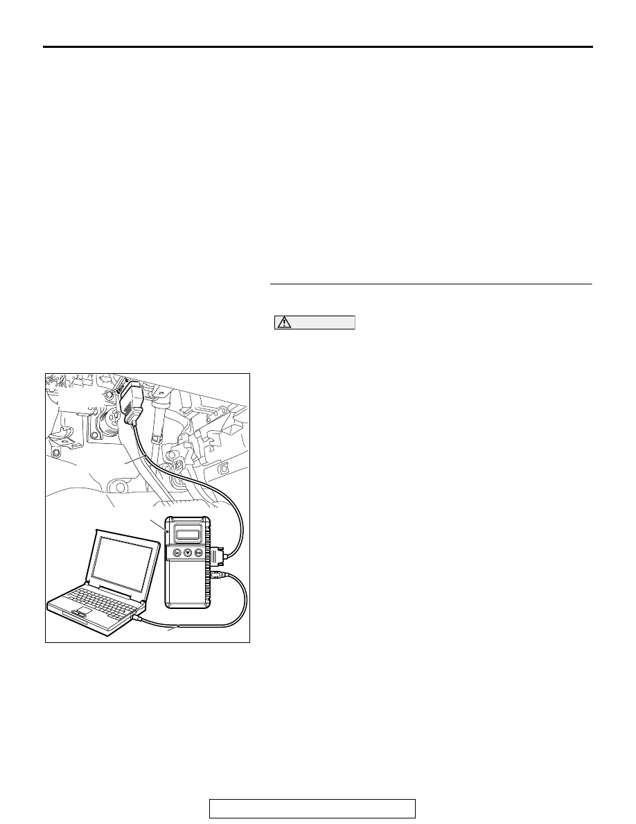
STEP 1. Using scan tool MB991958, diagnose the CAN bus 
line.

CAUTION

To prevent damage to scan tool MB991958, always turn the 
ignition switch to the "LOCK" (OFF) position before con-
necting or disconnecting scan tool MB991958.
(1) Connect scan tool MB991958. Refer to "How to connect the 

scan tool 

P.52B-28

."

(2) Turn the ignition switch to the "ON" position.
(3) Diagnose the CAN bus line.
(4) Turn the ignition switch to the "LOCK" (OFF) position.
Q: Is the CAN bus line found to be normal?

YES : Go to Step 2.
NO :  Repair the CAN bus line (Refer to GROUP 54C, 

Diagnosis 

P.54C-17

).

ZC501967

AC404789

AC701411AB

MB991824

MB991827

MB991910

Data link 
connector

SRS AIR BAG DIAGNOSIS

TSB Revision

SUPPLEMENTAL RESTRAINT SYSTEM (SRS)

52B-92

STEP 2. Recheck for diagnostic trouble code.
Check again if the DTC is set.
(1) Erase the DTC.
(2) Turn the ignition switch to the "ON" position.
(3) Check if the DTC is set.
(4) Turn the ignition switch to the "LOCK" (OFF) position.
Q: Is the DTC set?

YES : Go to Step 3.
NO :  There is an intermittent malfunction such as poor 

engaged connector(s) or open circuit (Refer to 
GROUP 00, How to Cope with Intermittent 
Malfunction 

P.00-15

).

ZC501967

AC404789

AC701411AB

MB991824

MB991827

MB991910

Data link 
connector

SRS AIR BAG DIAGNOSIS

TSB Revision

SUPPLEMENTAL RESTRAINT SYSTEM (SRS)

52B-93

STEP 3. Check the passenger's (front) air bag module. 
(Using scan tool MB991958, read the diagnostic trouble 
code.)
(1) Disconnect the negative battery terminal.
(2) Slide the outer housing of passenger’s (front) air bag 

module connector C-11 in the arrow direction shown, and 
disconnect the connector.

(3) Connect special tool MB991865 to special tool MB991866.

CAUTION

Do not insert a probe into the terminal from its front side 
directly, as the connector contact pressure may be weak-
ened.
(4) Insert special tool MB991866 into the harness side 

connector C-11 (terminal No.1 and 2 <1st squib> or terminal 
No.3 and 4 <2nd squib>) by backprobing.

(5) Connect the negative battery terminal.

CAUTION

Always DTC B1B0E is set when checking DTC B1B0A. This 
is because the second side terminal is isolated when 
checking it. DTC B1B0E is set but this is not a fault. In 
addition, always DTC B1B0A is set when checking DTC 
B1B0E because the first side terminal is isolated. 
(6) Erase the diagnostic trouble code memory, and check the 

diagnostic trouble code.

Q: Is the checked DTC set?

YES : Go to Step 4.
NO :  Replace the passenger's (front) air bag module. 

(Refer to 

P.52B-439

). Then go to Step 5.

AC701511

Outer housing of the passenger's (front) air bag
module connector


AC

AC701551AB

MB991865
(Dummy resistor: 3 

Ω) 

MB991866
(Resistor harness) 

C-11 Harness
side connector


C-11 Passenger's (front)
air bag module connector

SRS AIR BAG DIAGNOSIS

TSB Revision

SUPPLEMENTAL RESTRAINT SYSTEM (SRS)

52B-94

STEP 4. Check the harness for open circuit between 
SRS-ECU connector C-28 and the passenger's (front) air 
bag module connector C-11.
(1) Disconnect the negative battery terminal.
(2) While pushing the part "A" indicated in the figure of the 

harness side connector, turn the lock lever to the direction 
of the arrow to release the lock lever, and disconnect the 
C-28 SRS-ECU connector.

DANGER

To prevent the air bag from deploying unintentionally, 
disconnect the passenger’s (front) air bag module 
connector C-11 to short the squib circuit.

(3) Slide the outer housing of passenger’s (front) air bag 

module connector C-11 in the arrow direction shown, and 
disconnect the connector.

CAUTION

Insert an insulator such as a cable tie to a depth of 4 mm 
(0.16 inch) or more, otherwise the short spring will not be 
released.
(4) Insert a cable tie [3 mm (0.12 inch) wide, 0.5 mm (0.02 inch) 

thick] between terminals 7 and 8 <1st squib> or 11 and 12 
<2nd squib>, and the short spring to release the short 
spring.

AC506734

A

AB

Lock lever

AC701511

Outer housing of the passenger's (front) air bag
module connector


AC

AC701517AD

A

A

<1st Squib>

C-28 Harness side
connector (front view)

Section
A - A

Cable tie

Short spring

4 mm or more

Terminal

AC701517AE  

A

A

<2nd Squib>

Section
A - A

C-28 Harness side
connector (front view)

Cable tie

Short spring

4 mm or more

Terminal


Content   ..  1397  1398  1399  1400   ..