Mitsubishi Outlander GS45X. Manual - part 1373


  Index      Mitsubishi     Mitsubishi Outlander GS45X - service repair manual


Search            


Content   ..  1371  1372  1373  1374   ..


Mitsubishi Outlander GS45X. Manual - part 1373


OUTSIDE MIRROR

TSB Revision

EXTERIOR

51-115

.

CIRCUIT OPERATION

If either of the heated door mirror do not operate nor-
mally, it may be due to malfunctions in the heated 
door mirror circuit or door mirror.

.

TROUBLESHOOTING HINTS

• Malfunction of the heated door mirror circuit

• Malfunction of the door mirror

• The wiring harness or connectors may have 

loose, corroded or damaged terminals, or termi-
nals pushed back in the connector.

DIAGNOSIS

Required Special Tools:

• MB991223: Test Harness Set 

STEP 1. Verify the operation of each heated door mirror.
Q: Which door mirror does not heat?

Door mirror (LH) : Go to Step 2.
Door mirror (RH) : Go to Step 8.

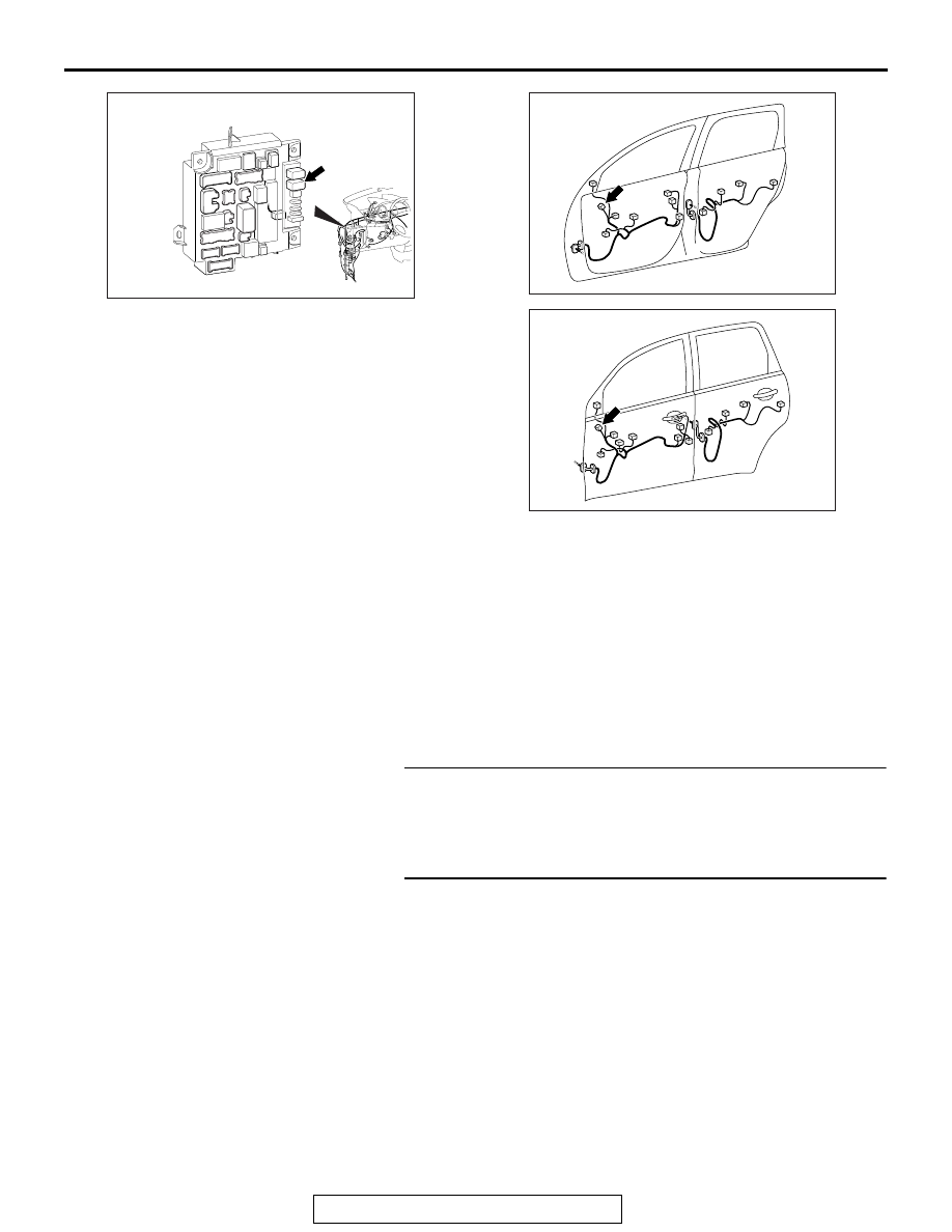
STEP 2. Check door mirror (LH) connector E-29 door 
mirror assembly for loose, corroded or damaged 
terminals, or terminals pushed back in the connector.
Q: Is door mirror (LH) connector E-29 door mirror 

assembly in good condition?
YES : 
Go to Step 3.
NO :  Repair or replace the damaged component(s). Refer 

to GROUP 00E, Harness Connector Inspection 

P.00E-2

. And then check to see that the heater 

function of the door mirror (LH) operates normally.

ACA02655 AG

C-306

Connector: C-306

AC605844

AZ

Connector: E-28

AC605845

BL

Connector: E-29

OUTSIDE MIRROR

TSB Revision

EXTERIOR

51-116

STEP 3. Check the heater of the door mirror (LH).

CAUTION

When relocating the car between locations of extremely 
different temperatures (warm and cold), leave the car in a 
location for a while to adapt to the temperature prior to 
checking it.
Check to see that the resistance between terminal 1 and 2 of 
the door mirror (LH) connector 9 of E-29 door mirror assembly.

• The resistance should be 7.2 ± 1.4 Ω at 25°C (77°F).

Q:  Is the resistance normal?

YES : Go to Step 4.
NO :  Replace the door mirror (LH). And then check to see 

that the heater function of the door mirror (LH) is 
operating normally.

STEP 4. Check the ground circuit between door mirror (LH) 
connector E-29 door mirror assembly and ground for open 
circuit. Measure the resistance at door mirror (LH) 
connector E-29 door mirror assembly. 
(1) Disconnect door mirror (LH) connector E-29 door mirror 

assembly and check at the wiring harness side connector.

(2) Measure the resistance value between terminal 1 and 

ground.

• The resistance should be 2Ω or less.

Q: Is the measured resistance 2

Ω or less?

YES : Go to Step 6.
NO :  Go to Step 5.

STEP 5. Check the wiring harness between door mirror 
(LH) connector E-29 door mirror assembly (terminal 1) and 
ground.
NOTE: Also check intermediate connector C-126 for loose, cor-
roded or damaged terminals, or terminals pushed back in the 
connector. If intermediate connector C-126 is damaged, repair 
or replace the damaged component(s) as described in GROUP 
00E, Harness Connector Inspection 

P.00E-2

.

Q: Is the wiring harness between door mirror (LH) 

connector E-29 door mirror assembly (terminal 1) and 
ground in good condition?
YES : 
No action is necessary and testing is complete.
NO :  The wiring harness may be damaged. Repair the 

wiring harness as necessary. And then check to see 
that the heater function of the door mirror (LH) 
operates normally.

AC900574 AC

AC702473 AU

Harness side: E-29

OUTSIDE MIRROR

TSB Revision

EXTERIOR

51-117

STEP 6. Check rear window defogger relay connector 
C-306 for loose, corroded or damaged terminal, or 
terminals pushed back in the connector.
Q:  Is rear window defogger relay connector C-306 in good 

condition?
YES : 
Go to Step 7.
NO :  Repair or replace the damaged component(s). Refer 

to GROUP 00E, Harness Connector Inspection 

P.00E-2

. And then check to see that the heater 

function of the door mirror (LH) operates normally.

STEP 7. Check the wiring harness between door mirror 
(LH) connector E-29 door mirror assembly (terminal 9) and 
rear window defogger relay connector C-306 (terminal 3).
NOTE: Also check intermediate connector C-127 for loose, cor-
roded or damaged terminals, or terminals pushed back in the 
connector. If intermediate connector C-127 is damaged, repair 
or replace the damaged component(s) as described in GROUP 
00E, Harness Connector Inspection 

P.00E-2

.

Q: Is the wiring harness between door mirror (LH) 

connector E-29 door mirror assembly (terminal 9) and 
rear window defogger relay connector C-306 (terminal 
3) in good condition?
YES : 
No action is necessary and testing is complete.
NO :  Repair the wiring harness as necessary. And then 

check to see that the heater function of the door 
mirror (LH) operates normally.

STEP 8. Check the door mirror (RH) connector E-28 door 
mirror assembly for loose, corroded or damaged 
terminals, or terminals pushed back in the connector.
Q: Is the door mirror (RH) connector E-28 door mirror 

assembly in good condition?
YES : 
Go to Step 9.
NO :  Repair or replace the damaged component(s). Refer 

to GROUP 00E, Harness Connector Inspection 

P.00E-2

. And then check to see that the heater 

function of the door mirror (RH) operates normally.

OUTSIDE MIRROR

TSB Revision

EXTERIOR

51-118

STEP 9. Check the heater function of the door mirror (RH).

CAUTION

When relocating the car between locations of extremely 
different temperatures (warm and cold), leave the car in a 
location for a while to adapt to the temperature prior to 
checking it.
Check to see that the resistance between terminal 1 and 2 of 
the door mirror (RH) connector E-28 door mirror assembly.

• The resistance should be 7.2 ± 1.4 Ω at 25°C (77°F).

Q:  Is the resistance normal?

YES : Go to Step 10.
NO :  Replace the door mirror (RH). And then check to see 

that the heater function of the door mirror (RH) 
operates normally.

STEP 10. Check the ground circuit between door mirror 
(RH) connector E-28 door mirror assembly and ground for 
open circuit. Measure the resistance at door mirror (RH) 
connector E-28 door mirror assembly.
(1) Disconnect door mirror (RH) connector E-28 door mirror 

assembly, and check at the wiring harness side connector.

(2) Measure the resistance value between terminal 1 and 

ground.

• The resistance should be 2Ω or less.

Q: Is the measured resistance 2

Ω or less?

YES : Go to Step 12.
NO :  Go to Step 11.

STEP 11. Check the wiring harness between door mirror 
(RH) connector E-28 door mirror assembly (terminal 1) and 
ground.
NOTE: Also check intermediate connector C-112 for loose, cor-
roded or damaged terminals, or terminals pushed back in the 
connector. If intermediate connector C-112 is damaged, repair 
or replace the damaged component(s) as described in GROUP 
00E, Harness Connector Inspection 

P.00E-2

.

Q: Is the wiring harness between door mirror (RH) 

connector E-28 door mirror assembly (terminal 1) and 
ground in good condition?
YES : 
No action is necessary and testing is complete.
NO :  The wiring harness may be damaged. Repair the 

wiring harness as necessary. And then check to see 
that the heater function of the door mirror (RH) 
operates normally.

AC900574 AD

AC702473 AW

Harness side: E-28


Content   ..  1371  1372  1373  1374   ..