Content .. 1344 1345 1346 1347 ..
Mitsubishi Outlander GS45X. Manual - part 1346
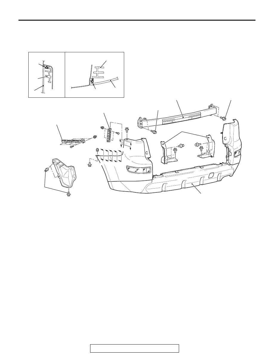
REAR BUMPER ASSEMBLY
TSB Revision
EXTERIOR
51-7
REAR BUMPER ASSEMBLY
REMOVAL AND INSTALLATION
M1511001901969
AC702393
1
5
3
AE
3
5
6
4
6
3
A
A
B
B
A
A
A
A
A
A
B
B
A
A
Section A – A
Section B – B
Claw
Claw
20 ± 5 N·m
15 ± 3 ft-lb
20 ± 5 N·m
15 ± 3 ft-lb
2
Removal steps
• Rear combination light (Refer to
GROUP 54A, Rear combination light
• Rear bumper harness connector
connection
1. Splash shield mounting clips
2. Rear bumper cover
3. Rear bumper assembly
4. Rear bumper beam assembly
5. Rear bumper side bracket
6. Rear bumper face side bracket
Removal steps (Continued)