Mitsubishi Outlander GS45X. Manual - part 1343


  Index      Mitsubishi     Mitsubishi Outlander GS45X - service repair manual


Search            


Content   ..  1341  1342  1343  1344   ..


Mitsubishi Outlander GS45X. Manual - part 1343


AWD-ECU

TSB Revision

ELECTRONIC CONTROL AWD

27C-95

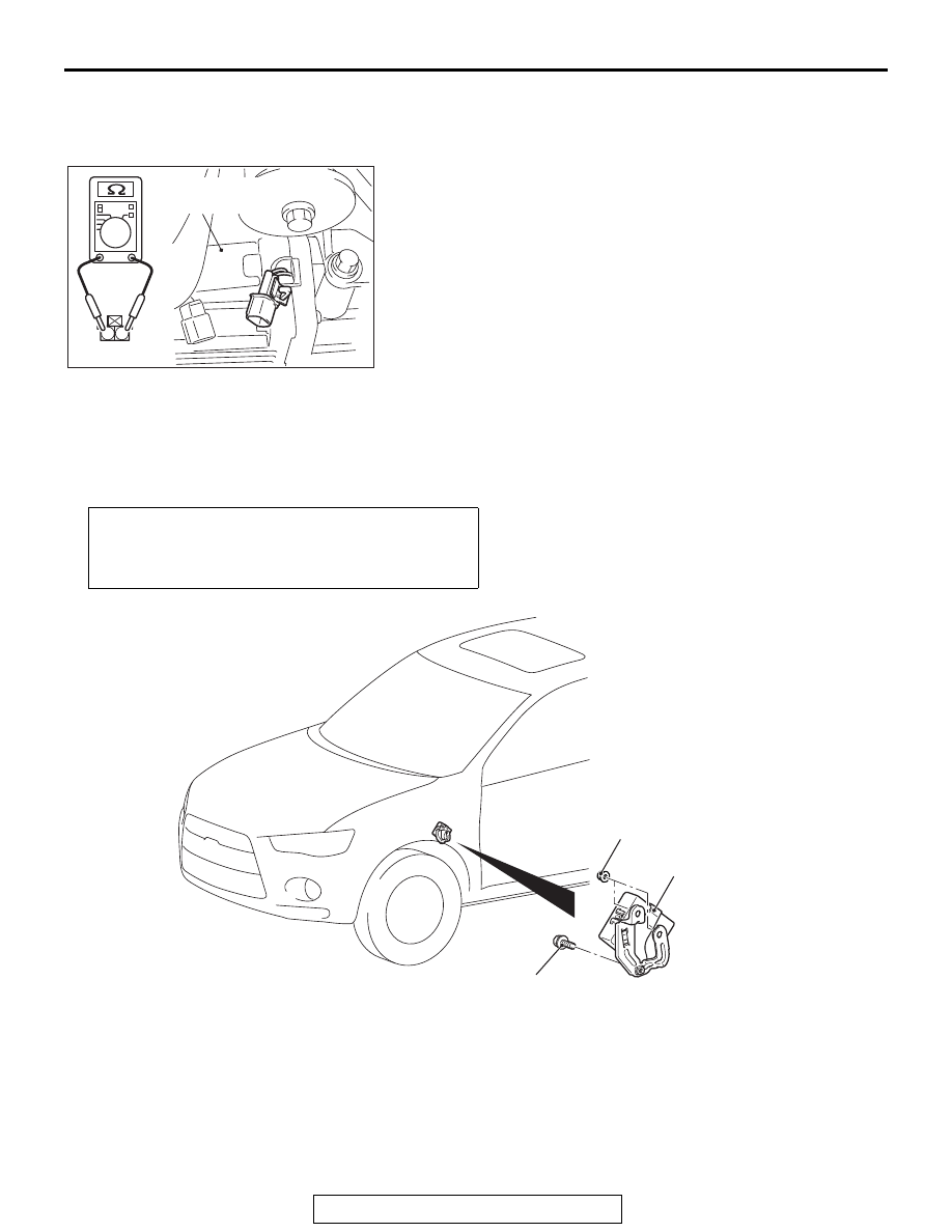
RESISTANCE MEASUREMENT BETWEEN 
ELECTRONIC CONTROL COUPLING SOLENOID 
CONNECTOR TERMINALS

Disconnect the D-119 connector, and measure the resistance 
value between the connector terminals on the electronic control 
coupling side. If the measured resistance value is out of the 
standard value range, replace the electronic control coupling. 
(Refer to 

P.27C-97

.)

Standard value: 2.2 

 4.0 Ω

AWD-ECU

REMOVAL AND INSTALLATION

M1274009200039

1

2

AC703685 AB

D-119

Electronic
control coupling

Pre-removal and post-installation operation
Removal and installation of the bottom cover assembly and 
glove box (Refer to GROUP 52A 

− Instrument Panel 

Assembly 

P.52A-2

.)

AC809407AC

AWD-ECU

11 ± 4 N·m
97 ± 35 in-lb

7.0 ± 3.0 N·m
62 ± 26 in-lb

DRIVE MODE SELECTOR

TSB Revision

ELECTRONIC CONTROL AWD

27C-96

DRIVE MODE SELECTOR

REMOVAL AND INSTALLATION

M1274007900087

Refer to GROUP 52A 

− Instrument Panel Assembly 

P.52A-2

.

DRIVE MODE SELECTOR CHECK

M1274008000065

AC703688AB

Drive mode 
selector

Switch position

Terminal 
number

Normal 
conditions

2WD (FWD)

− 2

Continuity 
exists (2 ohm 
or less).

− 3

No continuity

4WD (AWD)

− 2

No continuity

− 3

LOCK

− 2

No continuity

− 3

Continuity 
exists (2 ohm 
or less).

AC703686AB

ELECTRONIC CONTROL COUPLING

TSB Revision

ELECTRONIC CONTROL AWD

27C-97

ELECTRONIC CONTROL COUPLING

REMOVAL AND INSTALLATION

M1274002100138

INSTALLATION SERVICE POINT

.

>>A<< ELECTRONIC CONTROL COUPLING 
INSTALLATION

1. Check that the length of the electronic control coupling stud 

bolt (A) is within the standard value range.

Standard value: 22.3 

 25.1 mm (0.88  0.99 inch)

2. If it exceeds either of the limits, clean the threads for the 

electronic control coupling and replace the stud bolt.

Tightening torque: 15 

± 3 Nm (11 ± 2 ft-lb)

Removal steps 

1.

Propeller shaft assembly (Refer to 
GROUP 25 

− Propeller Shaft 

P.25-7

.)

2.

Cover

3.

Breather hose connection

4.

Connector connection

5.

Bracket

A

6.

Electronic control coupling

7.

Washer

AC905472

1

3

4

6

AE

2

7

5

Differential
side

Electronic control
coupling side

Semi-drying sealant: 
ThreeBond 1215, 1216, 1217 or 
equivalent

48 ± 6 N·m
36 ± 4 ft-lb

9.8 ± 1.9 N·m
87 ± 17 in-lb

54 ± 5 N·m
40 ± 3 ft-lb

AC703699AB

A

Electronic control 
coupling

NOTES


Content   ..  1341  1342  1343  1344   ..