Mitsubishi Outlander GS45X. Manual - part 133


  Index      Mitsubishi     Mitsubishi Outlander GS45X - service repair manual


Search            


Content   ..  131  132  133  134   ..


Mitsubishi Outlander GS45X. Manual - part 133


MMCS

TSB Revision

CHASSIS ELECTRICAL

54A-529

STEP 32. Check tweeter (LH) connector E-14 for loose, 
corroded or damaged terminals, or terminals pushed back 
in the connector.
Q: Is tweeter (LH) connector E-14 in good condition?

YES : Go to Step 33.
NO :  Repair or replace the damaged component(s). Refer 

to GROUP 00E, Harness Connector Inspection 

P.00E-2

.

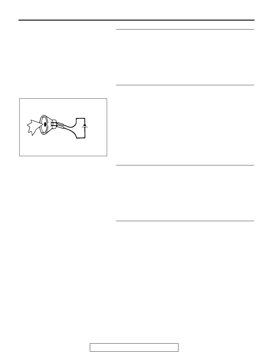
STEP 33. Check the tweeter (LH).
(1) Remove the tweeter (LH). Refer to 

P.54A-692

.

(2) Check that the tweeter (LH) outputs the noise when five 

volts are applied to the tweeter (LH) connector terminal.

Q: Does the tweeter (LH) output the noise?

YES : Go to Step 34.
NO :  Replace the tweeter (LH).

STEP 34. Check audio amplifier connector D-127 for loose, 
corroded or damaged terminals, or terminals pushed back 
in the connector.
Q: Is audio amplifier connector D-127 in good condition?

YES : Go to Step 35.
NO :  Repair or replace the damaged component(s). Refer 

to GROUP 00E, Harness Connector Inspection 

P.00E-2

.

STEP 35. Check the wiring harness between audio 
amplifier connector D-127 (terminal 6, 14) and tweeter (LH) 
connector E-14 (terminal 2, 1).
NOTE: Also check intermediate connectors C-22 and C-127 for 
loose, corroded, or damaged terminals, or terminals pushed 
back in the connector. If intermediate connector C-22 or C-127 
is damaged, repair or replace the connector as described in 
GROUP 00E, Harness Connector Inspection 

P.00E-2

.

• Check the communication lines for open circuit and short 

circuit.

Q: Is the wiring harness between audio amplifier connector 

D-127 (terminal 6, 14) and tweeter (LH) connector E-14 
(terminal 2, 1) in good condition?
YES : 
Check the trouble symptom, and go to Step 40.
NO :  The wiring harness may be damaged or the 

connector(s) may have loose, corroded or damaged 
terminals, or terminals pushed back in the connector. 
Repair the wiring harness as necessary. 

AC703723AB

5 volts

MMCS

TSB Revision

CHASSIS ELECTRICAL

54A-530

STEP 36. Check subwoofer connector D-15 for loose, 
corroded or damaged terminals, or terminals pushed back 
in the connector.
Q: Is subwoofer connector D-15 in good condition?

YES : Go to Step 37.
NO :  Repair or replace the damaged component(s). Refer 

to GROUP 00E, Harness Connector Inspection 

P.00E-2

.

STEP 37. Check the Subwoofer.
(1) Remove the subwoofer. Refer to 

P.54A-692

.

(2) Check that the subwoofer outputs the noise when five volts 

are applied to the subwoofer connector terminal.

Q: Does the subwoofer output the noise?

YES : Go to Step 38.
NO :  Replace the subwoofer.

STEP 38. Check audio amplifier connector D-126 for loose, 
corroded or damaged terminals, or terminals pushed back 
in the connector.
Q: Is audio amplifier connector D-126 in good condition?

YES : Go to Step 39.
NO :  Repair or replace the damaged component(s). Refer 

to GROUP 00E, Harness Connector Inspection 

P.00E-2

.

AC703728AB

5 volts

MMCS

TSB Revision

CHASSIS ELECTRICAL

54A-531

STEP 39. Check the wiring harness between audio 
amplifier connector D-126 (terminal 21, 22, 29, 30) and 
subwoofer connector D-15 (terminal 4, 2, 3, 1).

• Check the communication lines for open circuit and short 

circuit.

Q: Is the wiring harness between audio amplifier connector 

D-126 (terminal 21, 22, 29, 30) and subwoofer connector 
D-15 (terminal 4, 2, 3, 1) in good condition?
YES : 
Check the trouble symptom, and go to Step 40.
NO :  The wiring harness may be damaged or the 

connector(s) may have loose, corroded or damaged 
terminals, or terminals pushed back in the connector. 
Repair the wiring harness as necessary. 

STEP 40. Replace the audio amplifier temporarily, and 
check the trouble symptom.
Replace the audio amplifier temporarily, and check that the 
sound is output from the speaker.
Q: Is the check result normal?

YES : The trouble can be an intermittent malfunction (Refer 

to GROUP 00, How to use 
Troubleshooting/inspection Service Points, How to 
Cope with Intermittent Malfunction 

P.00-15

).

NO :  Replace the multivision display.

Inspection Procedure 4: The navigation system can be operated while the vehicle is driven.

CAUTION

Before replacing the multivision display, ensure that the power supply circuit, the ground circuit, and 
the communication circuit are normal. (Check that the voltage is 10 V or more.)

Multivision Display Communication Circuit

COMBINATION 
METER

INTERFACE 
CIRCUIT

MULTIVISION 
DISPLAY

MMCS

TSB Revision

CHASSIS ELECTRICAL

54A-532

.

COMMENTS ON TROUBLE SYMPTOM

There is a failure in the wiring harness between the 
combination meter and the multivision display, the 
respective connector(s), the combination meter or 
the multivision display.

.

PROBABLE CAUSES

• Malfunctions of combination meter

• Malfunctions of multivision display

• Damaged harness wires and connectors

DIAGNOSIS

Required Special Tools:

• MB991223: Harness Set

• MB992006: Extra Fine Probe

STEP 1. Perform "Vehicle Signal Check" in the MMCS 
service mode.
Perform "Vehicle Signal Check" in the MMCS service mode to 
check whether vehicle speed signal is normal. (Refer to 

P.54A-443

.)

Q: Is the vehicle speed signal transmitted normally?

YES : Replace the multivision display.
NO :  Go to Step 2.

STEP 2. Check the speed meter.
Check whether the speedometer works normally.
Q: Does the speed meter work normally?

YES : Go to Step 3.
NO :  Diagnose the combination meter. Refer to 

P.54A-34

.

STEP 3. Check combination meter connector C-03 and 
multivision display connector C-10 for loose, corroded or 
damaged terminals, or terminals pushed back in the 
connector.
Q: Is combination meter connector C-03 or multivision 

display connector C-10 in good condition?
YES : 
Go to Step 4.
NO :  Repair or replace the damaged component(s). Refer 

to GROUP 00E, Harness Connector Inspection 

P.00E-2

.

ACA02653AC

Connector: C-03

AC703148AN

Connectors: C-10, C-17

C-17

C-10


Content   ..  131  132  133  134   ..