Mitsubishi Outlander GS45X. Manual - part 1310


  Index      Mitsubishi     Mitsubishi Outlander GS45X - service repair manual


Search            


Content   ..  1308  1309  1310  1311   ..


Mitsubishi Outlander GS45X. Manual - part 1310


DIAGNOSIS

TSB Revision

CONTROLLER AREA NETWORK (CAN)

54C-185

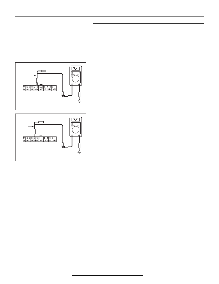
STEP 12. Check the wiring harness between ETACS-ECU 
connector C-301 and body ground for a short to power 
supply. Measure the voltage at ETACS-ECU connector 
C-301.
(1) Disconnect ETACS-ECU connector C-301, and measure 

the voltage at the wiring harness side of ETACS-ECU 
connector.

(2) Turn the ignition switch to the ON position.
(3) Measure the voltage between ETACS-ECU connector 

terminal 6 and body ground.

OK: 4.7 volts or less

(4) Measure the voltage between ETACS-ECU connector 

terminal 7 and body ground.

OK: 4.7 volts or less

Q: Do all the voltages measure 4.7 volts or less?

YES : Go to Step 23.
NO :  Go to Step 13.

AC702831BO

Harness side: C-301

Test 
harness

AC702831 BP

Harness side: C-301

Test 
harness

DIAGNOSIS

TSB Revision

CONTROLLER AREA NETWORK (CAN)

54C-186

STEP 13. Check the wiring harness between joint 
connector (CAN1) C-103 and combination meter connector 
C-03 for a short to power supply. Measure the voltage at 
joint connector (CAN1) C-103.
(1) Disconnect joint connector (CAN1), and measure the 

voltage at the wiring harness side of joint connector 
(CAN1).

(2) Connect the negative battery terminal.
(3) Turn the ignition switch to the ON position.
(4) Measure the voltage between joint connector (CAN1) 

terminal 4 and body ground.

OK: 4.7 volts or less

(5) Measure the voltage between joint connector (CAN1) 

terminal 15 and body ground.

OK: 4.7 volts or less

Q: Do all the voltages measure 4.7 volts or less?

YES (vehicles with KOS) : Go to Step 14.
YES (vehicles with WCM) : Go to Step 15.
NO (vehicles with KOS and WCM) : Go to Step 44.

AC702831 CW

Harness side: C-103

Test 
harness

AC702831CX

Harness side: C-103

Test 
harness

DIAGNOSIS

TSB Revision

CONTROLLER AREA NETWORK (CAN)

54C-187

STEP 14. Check the wiring harness between joint 
connector (CAN1) C-103 and KOS-ECU connector C-102 
for a short to power supply. Measure the voltage at joint 
connector (CAN1) C-103.
(1) Disconnect joint connector (CAN1), and measure the 

voltage at the wiring harness side of joint connector 
(CAN1).

(2) Turn the ignition switch to the ON position.
(3) Measure the voltage between joint connector (CAN1) 

terminal 8 and body ground.

OK: 4.7 volts or less

(4) Measure the voltage between joint connector (CAN1) 

terminal 21 and body ground.

OK: 4.7 volts or less

Q: Do all the voltages measure 4.7 volts or less?

YES : Go to Step 16.
NO :  Go to Step 45.

AC702831BT

Harness side: C-103

Test harness

AC702831BU

Harness side: C-103

Test harness

DIAGNOSIS

TSB Revision

CONTROLLER AREA NETWORK (CAN)

54C-188

STEP 15. Check the wiring harness between joint 
connector (CAN1) C-103 and WCM connector C-29 for a 
short to power supply. Measure the voltage at joint 
connector (CAN1) C-103.
(1) Disconnect joint connector (CAN1), and measure the 

voltage at the wiring harness side of joint connector 
(CAN1).

(2) Turn the ignition switch to the ON position.
(3) Measure the voltage between joint connector (CAN1) 

terminal 5 and body ground.

OK: 4.7 volts or less

(4) Measure the voltage between joint connector (CAN1) 

terminal 16 and body ground.

OK: 4.7 volts or less

Q: Do all the voltages measure 4.7 volts or less?

YES : Go to Step 16.
NO :  Go to Step 46.

AC702831 BV

Harness side: C-103

Test 
harness

AC702831 BW

Harness side: C-103

Test 
harness


Content   ..  1308  1309  1310  1311   ..