Mitsubishi Outlander GS45X. Manual - part 1308


  Index      Mitsubishi     Mitsubishi Outlander GS45X - service repair manual


Search            


Content   ..  1306  1307  1308  1309   ..


Mitsubishi Outlander GS45X. Manual - part 1308


DIAGNOSIS

TSB Revision

CONTROLLER AREA NETWORK (CAN)

54C-177

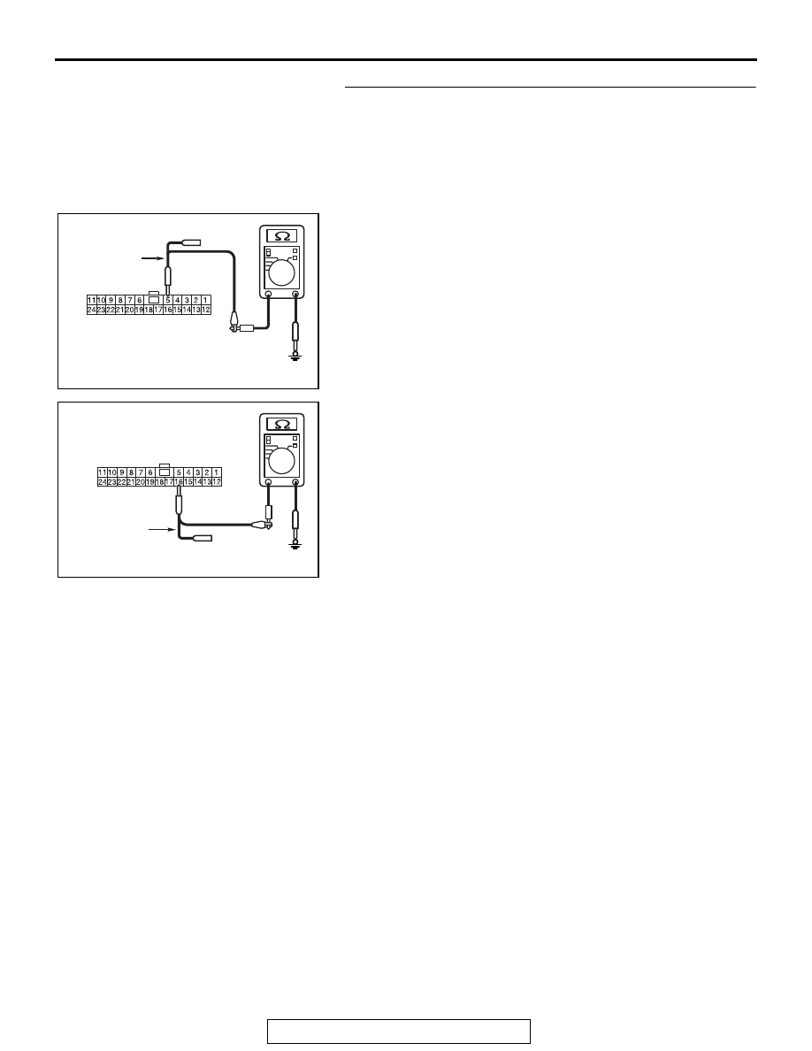
STEP 4. Check the wiring harness between joint connector 
(CAN1) C-103 and WCM connector C-29 for a short to 
ground. Measure the resistance at joint connector (CAN1) 
C-103.
(1) Disconnect joint connector (CAN1), and measure the 

resistance at the wiring harness side of joint connector 
(CAN1).

(2) Measure the resistance between joint connector (CAN1) 

terminal 5 and body ground.

OK: 1 k

Ω or more

(3) Measure the resistance between joint connector (CAN1) 

terminal 16 and body ground.

OK: 1 k

Ω or more

Q: Do all the resistances measure 1 k

Ω or more?

YES : Go to Step 5.
NO :  Go to Step 46.

AC702818 CD

Harness side: C-103

Test 
harness

AC702818 CE

Harness side: C-103

Test 
harness

DIAGNOSIS

TSB Revision

CONTROLLER AREA NETWORK (CAN)

54C-178

STEP 5. Check the wiring harness between joint connector 
(CAN1) C-103 and SRS-ECU connector C-28 for a short to 
ground. Measure the resistance at joint connector (CAN1) 
C-103.
(1) Disconnect joint connector (CAN1), and measure the 

resistance at the wiring harness side of joint connector 
(CAN1).

(2) Measure the resistance between joint connector (CAN1) 

terminal 2 and body ground.

OK: 1 k

Ω or more

(3) Measure the resistance between joint connector (CAN1) 

terminal 13 and body ground.

OK: 1 k

Ω or more

Q: Do all the resistances measure 1 k

Ω or more?

YES : Go to Step 6.
NO :  Go to Step 47.

AC702818 CP

Harness side: C-103

Test 
harness

AC702818CQ

Harness side: C-103

Test 
harness

DIAGNOSIS

TSB Revision

CONTROLLER AREA NETWORK (CAN)

54C-179

STEP 6. Check the wiring harness between joint connector 
(CAN1) C-103 and occupant classification-ECU connector 
D-34-2 for a short to ground. Measure the resistance at 
joint connector (CAN1) C-103.
(1) Disconnect joint connector (CAN1), and measure the 

resistance at the wiring harness side of joint connector 
(CAN1).

(2) Measure the resistance between joint connector (CAN1) 

terminal 11 and body ground.

OK: 1 k

Ω or more

(3) Measure the resistance between joint connector (CAN1) 

terminal 24 and body ground.

OK: 1 k

Ω or more

Q: Do all the resistances measure 1 k

Ω or more?

YES : Go to Step 7.
NO  :  Go to Step 48.

AC702818 CH

Harness side: C-103

Test harness

AC702818 CI

Harness side: C-103

Test harness

DIAGNOSIS

TSB Revision

CONTROLLER AREA NETWORK (CAN)

54C-180

STEP 7. Check the wiring harness between joint connector 
(CAN1) C-103 and A/C-ECU connector C-109 for a short to 
ground. Measure the resistance at joint connector (CAN1) 
C-103.
(1) Disconnect joint connector (CAN1), and measure the 

resistance at the wiring harness side of joint connector 
(CAN1).

(2) Measure the resistance between joint connector (CAN1) 

terminal 9 and body ground.

OK: 1 k

Ω or more

(3) Measure the resistance between joint connector (CAN1) 

terminal 22 and body ground.

OK: 1 k

Ω or more

Q: Do all the resistances measure 1 k

Ω or more?

YES (vehicles without MMCS) : Go to Step 8.
YES (vehicles with MMCS) : Go to Step 9.
NO  :  Go to Step 49.

AC702818 CL

Harness side: C-103

Test harness

AC702818 CM

Harness side: C-103

Test harness


Content   ..  1306  1307  1308  1309   ..