Mitsubishi Outlander GS45X. Manual - part 1298


  Index      Mitsubishi     Mitsubishi Outlander GS45X - service repair manual


Search            


Content   ..  1296  1297  1298  1299   ..


Mitsubishi Outlander GS45X. Manual - part 1298


DIAGNOSIS

TSB Revision

CONTROLLER AREA NETWORK (CAN)

54C-137

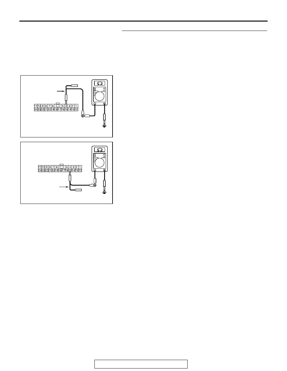
STEP 2. Check the wiring harness between joint connector 
(CAN1) C-103 and combination meter connector C-03 for a 
short to ground. Measure the resistance at joint connector 
(CAN1) C-103.
(1) Disconnect joint connector (CAN1), and measure the 

resistance at the wiring harness side of joint connector 
(CAN1).

(2) Measure the resistance between joint connector (CAN1) 

terminal 4 and body ground.

OK: 1 k

Ω or more

(3) Measure the resistance between joint connector (CAN1) 

terminal 15 and body ground.

OK: 1 k

Ω or more

Q: Do all the resistances measure 1 k

Ω or more?

YES (vehicles with KOS)  : Go to Step 3.
YES (vehicles with WCM)  : Go to Step 4.
NO (vehicles with KOS or WCM)  : Go to Step 22.

AC702818 DP

Harness side: C-103

Test 
harness

AC702818 DQ

Harness side: C-103

Test 
harness

DIAGNOSIS

TSB Revision

CONTROLLER AREA NETWORK (CAN)

54C-138

STEP 3. Check the wiring harness between joint connector 
(CAN1) C-103 and KOS-ECU connector C-102 for a short to 
ground. Measure the resistance at joint connector (CAN1) 
C-103.
(1) Disconnect joint connector (CAN1), and measure the 

resistance at the wiring harness side of joint connector 
(CAN1).

(2) Measure the resistance between joint connector (CAN1) 

terminal 8 and body ground.

OK: 1 k

Ω or more

(3) Measure the resistance between joint connector (CAN1) 

terminal 21 and body ground.

OK: 1 k

Ω or more

Q: Do all the resistances measure 1 k

Ω or more?

YES : Go to Step 5.
NO :  Go to Step 23.

AC702818 CB

Harness side: C-103

Test harness

AC702818 CC

Harness side: C-103

Test harness

DIAGNOSIS

TSB Revision

CONTROLLER AREA NETWORK (CAN)

54C-139

STEP 4. Check the wiring harness between joint connector 
(CAN1) C-103 and WCM connector C-29 for a short to 
ground. Measure the resistance at joint connector (CAN1) 
C-103.
(1) Disconnect joint connector (CAN1), and measure the 

resistance at the wiring harness side of joint connector 
(CAN1).

(2) Measure the resistance between joint connector (CAN1) 

terminal 5 and body ground.

OK: 1 k

Ω or more

(3) Measure the resistance between joint connector (CAN1) 

terminal 16 and body ground.

OK: 1 k

Ω or more

Q: Do all the resistances measure 1 k

Ω or more?

YES : Go to Step 5.
NO :  Go to Step 24.

AC702818 CD

Harness side: C-103

Test 
harness

AC702818 CE

Harness side: C-103

Test 
harness

DIAGNOSIS

TSB Revision

CONTROLLER AREA NETWORK (CAN)

54C-140

STEP 5. Check the wiring harness between joint connector 
(CAN1) C-103 and SRS-ECU connector C-28 for a short to 
ground. Measure the resistance at joint connector (CAN1) 
C-103.
(1) Disconnect joint connector (CAN1), and measure the 

resistance at the wiring harness side of joint connector 
(CAN1).

(2) Measure the resistance between joint connector (CAN1) 

terminal 2 and body ground.

OK: 1 k

Ω or more

(3) Measure the resistance between joint connector (CAN1) 

terminal 13 and body ground.

OK: 1 k

Ω or more

Q: Do all the resistances measure 1 k

Ω or more?

YES : Go to Step 6.
NO :  Go to Step 25.

AC702818 CP

Harness side: C-103

Test 
harness

AC702818CQ

Harness side: C-103

Test 
harness


Content   ..  1296  1297  1298  1299   ..