Mitsubishi Outlander GS45X. Manual - part 1279


  Index      Mitsubishi     Mitsubishi Outlander GS45X - service repair manual


Search            


Content   ..  1277  1278  1279  1280   ..


Mitsubishi Outlander GS45X. Manual - part 1279


DIAGNOSIS

TSB Revision

CONTROLLER AREA NETWORK (CAN)

54C-61

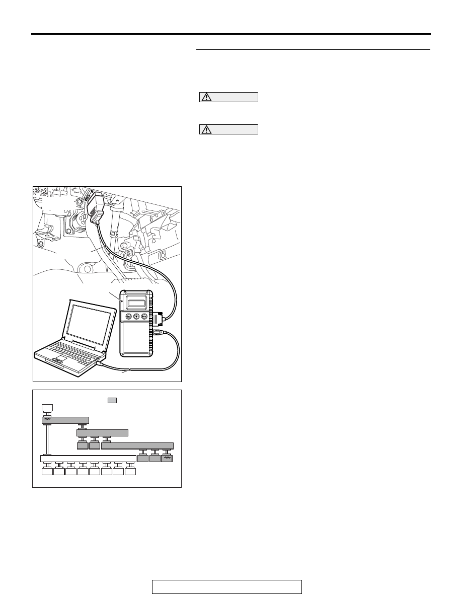
STEP 13. Using scan tool MB991958, diagnose the CAN 
bus line. (checking the ABS-ECU <vehicles without ASC> 
or ASC-ECU <vehicles with ASC> for internal short to 
ground)

CAUTION

Strictly observe the specified wiring harness repair proce-
dure. For details refer to 

P.54C-7

.

CAUTION

To prevent damage to scan tool MB991958, always turn the 
ignition switch to the "LOCK" (OFF) position before con-
necting or disconnecting scan tool MB991958.
(1) Disconnect ABS-ECU connector A-01 <vehicles without 

ASC> or ASC-ECU connector A-02 <vehicles with ASC>.

(2) Connect scan tool MB991958 to the data link connector.
(3) Turn the ignition switch to the "ON" position.

(4) Diagnose CAN bus lines, and check if the scan tool 

MB991958 screen is as shown in the figure.

OK: The display of the scan tool MB991958 is as 
shown in the figure.

Q: Does scan tool MB991958 screen correspond to the 

illustration?
YES : 
Repair the wiring harness between ABS-ECU 

connector A-01 <vehicles without ASC> or ASC-ECU 
connector A-02 <vehicles with ASC> and joint 
connector (CAN3) C-01.

NO :  Check ABS-ECU connector A-01 <vehicles without 

ASC> or ASC-ECU connector A-02 <vehicles with 
ASC>, and repair if necessary. If the ABS-ECU 
connector <vehicles without ASC> or ASC-ECU 
connector <vehicles with ASC> is in good condition, 
replace the ABS-ECU <vehicles without ASC> or 
ASC-ECU <vehicles with ASC>.

ZC501967

AC404789

AC702802

MB991824

MB991827

MB991910

Data link

connector

AB

ACA02847AC

: Red section on screen

M.U.T.

F.A.S.T.
/WCM

SRS

OCM

A/C

AUDIO

MMCS

Sat Radio

METER

JC

ETACS

JC

JC

SAS

AWC

ABS/ASC

AT/CVT

ENGINE

DIAGNOSIS

TSB Revision

CONTROLLER AREA NETWORK (CAN)

54C-62

STEP 14. Using scan tool MB991958, diagnose the CAN 
bus line. (checking the TCM for internal short to ground)

CAUTION

Strictly observe the specified wiring harness repair proce-
dure. For details refer to 

P.54C-7

.

CAUTION

To prevent damage to scan tool MB991958, always turn the 
ignition switch to the "LOCK" (OFF) position before con-
necting or disconnecting scan tool MB991958.
(1) Disconnect TCM connector C-38.
(2) Connect scan tool MB991958 to the data link connector.
(3) Turn the ignition switch to the "ON" position.

(4) Diagnose CAN bus lines, and check if the scan tool 

MB991958 screen is as shown in the figure.

OK: The display of the scan tool MB991958 is as 
shown in the figure.

Q: Does scan tool MB991958 screen correspond to the 

illustration?
YES : 
Repair the wiring harness between TCM connector 

C-38 and joint connector (CAN3) C-01.

NO :  Check TCM connector C-38, and repair if necessary. 

If the TCM connector is in good condition, replace the 
TCM.

ZC501967

AC404789

AC702802

MB991824

MB991827

MB991910

Data link

connector

AB

ACA02847AC

: Red section on screen

M.U.T.

F.A.S.T.
/WCM

SRS

OCM

A/C

AUDIO

MMCS

Sat Radio

METER

JC

ETACS

JC

JC

SAS

AWC

ABS/ASC

AT/CVT

ENGINE

DIAGNOSIS

TSB Revision

CONTROLLER AREA NETWORK (CAN)

54C-63

DIAGNOSTIC ITEM 5: Diagnose shorts in the power supply to CAN-C bus line.

CAUTION

When servicing a CAN bus line, ground yourself by touching a metal object such as an unpainted 
water pipe. If you fail to do so, a component connected to the CAN bus line may be damaged.

CAN Communication Circuit

ETACS-ECU

INTERFACE 
CIRCUIT

CAN DRIVE 
CIRCUIT

STEERING WHEEL 
SENSOR

AWD-ECU

AWC-ECU

JOINT CONNECTOR 
(CAN2)

JOINT CONNECTOR 
(CAN3)

TRANSAXLE 
CONTROL MODULE

ASC-ECU

ABS-ECU

ENGINE CONTROL 
MODULE

:VEHICLES WITHOUT ASC

NOTE

:VEHICLES WITH ASC

:6A/T

:CVT

:ELECTRONIC CONTROLLED AWD
:S-AWC

DIAGNOSIS

TSB Revision

CONTROLLER AREA NETWORK (CAN)

54C-64

.

FUNCTION

If a short to power supply is present in the CAN-C 
lines, this diagnosis result will be set.

.

TROUBLE JUDGMENT CONDITIONS

The wiring harness wire or connectors may have 
loose, corroded, or damage terminals, or terminals 
pushed back in the connector, or an ECU may be 
defective.

.

TROUBLESHOOTING HINTS

• Malfunction of the connector (short to power sup-

ply in connector)

• Malfunction of the wiring harness (short to power 

supply in the CAN-C main or sub bus lines)

• Malfunction of the ECU (ETACS-ECU, or ECUs 

on CAN-C lines failed)

DIAGNOSIS

Required Special Tools:

• MB991223: Harness Set

• MB992006: Extra Fine Probe

• MB991958: Scan Tool (M.U.T.-III Sub Assembly)

• MB991824: Vehicle Communication Interface (V.C.I.)

• MB991827: M.U.T.-III USB Cable

• MB991910: M.U.T.-III Main Harness A

AC901112

Connectors: A-01, A-02

A-01 (B), 
A-02 (B)

AD

AC901598

Connector: B-11

AB

B-11 (GR)

AC901075 AN

C-01

C-04

C-31

C-33

C-38

Connectors: C-01, C-04, C-31, C-33, C-38, 
C-128, C-138, C-139

C-128, 
C-139

C-138 (BR)

AC900844AV

Connector: C-209

ACA02655BB

Connector: C-301


Content   ..  1277  1278  1279  1280   ..