Mitsubishi Outlander GS45X. Manual - part 1277


  Index      Mitsubishi     Mitsubishi Outlander GS45X - service repair manual


Search            


Content   ..  1275  1276  1277  1278   ..


Mitsubishi Outlander GS45X. Manual - part 1277


DIAGNOSIS

TSB Revision

CONTROLLER AREA NETWORK (CAN)

54C-53

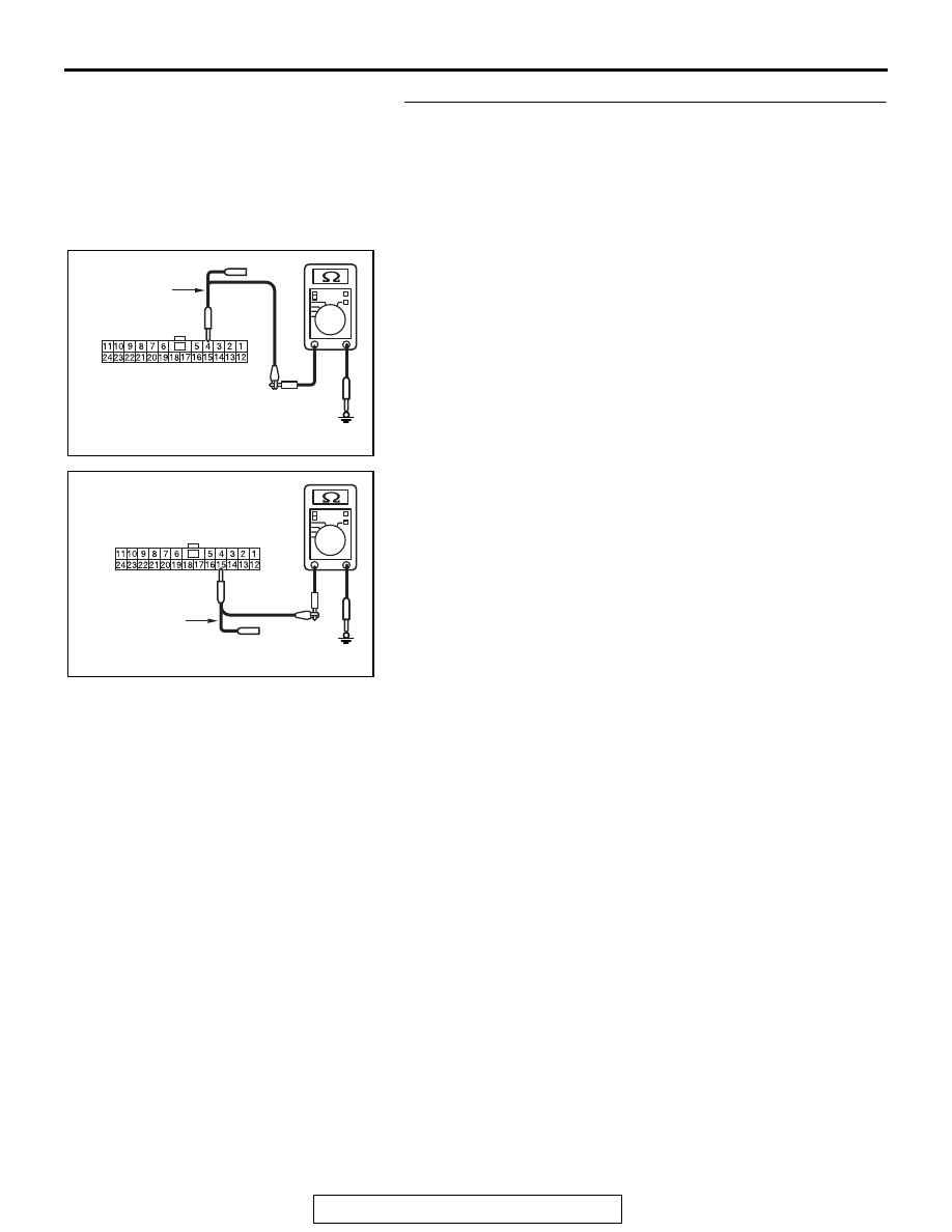
STEP 5. Check the wiring harness between joint connector 
(CAN3) C-01 and ECM connector B-11 for a short to 
ground. Measure the resistance at joint connector (CAN3) 
C-01.
(1) Disconnect joint connector (CAN3), and measure the 

resistance at the wiring harness side of joint connector 
(CAN3).

(2) Measure the resistance between joint connector (CAN3) 

terminal 4 and body ground.

OK: 1 k

Ω or more

(3) Measure the resistance between joint connector (CAN3) 

terminal 15 and body ground.

OK: 1 k

Ω or more

Q: Do all the resistances measure 1 k

Ω or more?

YES : Go to Step 6.
NO :  Go to Step 12.

AC702818 BT

Harness side: C-01

Test 
harness

AC702818 BU

Harness side: C-01

Test 
harness

DIAGNOSIS

TSB Revision

CONTROLLER AREA NETWORK (CAN)

54C-54

STEP 6. Check the wiring harness between joint connector 
(CAN3) C-01 and ABS-ECU connector A-01 <vehicles 
without ASC> or ASC-ECU connector A-02 <vehicles with 
ASC> for a short to ground. Measure the resistance at joint 
connector (CAN3) C-01.
(1) Disconnect joint connector (CAN3), and measure the 

resistance at the wiring harness side of joint connector 
(CAN3).

(2) Measure the resistance between joint connector (CAN3) 

terminal 6 and body ground.

OK: 1 k

Ω or more

(3) Measure the resistance between joint connector (CAN3) 

terminal 19 and body ground.

OK: 1 k

Ω or more

Q: Do all the resistances measure 1 k

Ω or more?

YES <CVT, A/T> : Go to Step 7.
YES <M/T> : Check intermediate connector C-33, and 

repair if necessary. If the intermediate connector is in 
good condition, repair the wiring harness between 
joint connector (CAN2) C-04 and joint connector 
(CAN3) C-01.

NO  :  Go to Step 13.

AC702818BV

Harness side: C-01

Test harness

AC702818 BW

Harness side: C-01

Test 
harness

DIAGNOSIS

TSB Revision

CONTROLLER AREA NETWORK (CAN)

54C-55

STEP 7. Check the wiring harness between joint connector 
(CAN3) C-01 and TCM connector C-38 for a short to 
ground. Measure the resistance at joint connector (CAN3) 
C-01.
(1) Disconnect joint connector (CAN3), and measure the 

resistance at the wiring harness side of joint connector 
(CAN3).

(2) Measure the resistance between joint connector (CAN3) 

terminal 7 and body ground.

OK: 1 k

Ω or more

(3) Measure the resistance between joint connector (CAN3) 

terminal 20 and body ground.

OK: 1 k

Ω or more

Q: Do all the resistances measure 1 k

Ω or more?

YES : Check intermediate connector C-27, and repair if 

necessary. If the intermediate connector is in good 
condition, repair the wiring harness between joint 
connector (CAN2) C-04 and joint connector (CAN3) 
C-01.

NO :  Go to Step 14.

AC702818BX

Harness side: C-01

Test harness

AC702818 BY

Harness side: C-01

Test 
harness

DIAGNOSIS

TSB Revision

CONTROLLER AREA NETWORK (CAN)

54C-56

STEP 8. Using scan tool MB991958, diagnose the CAN bus 
line. (checking the steering wheel sensor for internal short 
to ground)

CAUTION

Strictly observe the specified wiring harness repair proce-
dure. For details refer to 

P.54C-7

.

CAUTION

To prevent damage to scan tool MB991958, always turn the 
ignition switch to the "LOCK" (OFF) position before con-
necting or disconnecting scan tool MB991958.
(1) Disconnect steering wheel sensor connector C-209.
(2) Connect scan tool MB991958 to the data link connector.
(3) Turn the ignition switch to the "ON" position.

(4) Diagnose CAN bus lines, and check if the scan tool 

MB991958 screen is as shown in the figure.

OK: The display of the scan tool MB991958 is as 
shown in the figure.

Q: Does scan tool MB991958 screen correspond to the 

illustration?
YES : 
Repair the wiring harness between steering wheel 

sensor connector C-209 and joint connector (CAN2) 
C-04.

NO :  Check steering wheel sensor connector C-209, and 

repair if necessary. If the steering wheel sensor 
connector is in good condition, replace the steering 
wheel sensor.

ZC501967

AC404789

AC702802

MB991824

MB991827

MB991910

Data link

connector

AB

ACA02847AC

: Red section on screen

M.U.T.

F.A.S.T.
/WCM

SRS

OCM

A/C

AUDIO

MMCS

Sat Radio

METER

JC

ETACS

JC

JC

SAS

AWC

ABS/ASC

AT/CVT

ENGINE


Content   ..  1275  1276  1277  1278   ..