Mitsubishi Outlander GS45X. Manual - part 1267


  Index      Mitsubishi     Mitsubishi Outlander GS45X - service repair manual


Search            


Content   ..  1265  1266  1267  1268   ..


Mitsubishi Outlander GS45X. Manual - part 1267


EXPLANATION ABOUT THE SCAN TOOL (M.U.T.-III) CAN BUS DIAGNOSTICS

TSB Revision

CONTROLLER AREA NETWORK (CAN)

54C-13

2. Pinpoint possible trouble spot according to 

diagnostic trouble code

If diagnostic trouble code related to CAN 
communication is set as past trouble, isolate 
opens as described below.
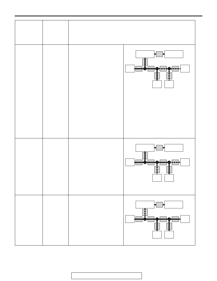
ECU C and 
ECU D

Trouble in 
CAN bus line 
(d)

ECUs C and D communicate 
with scan tool MB991958 via 
CAN bus lines (b), (c), (d), (e) 
and (g). Scan tool MB991958 
judges that CAN bus lines (b) 
and (c) are normal, because it 
can communicate with ECU B. 
Possible trouble may be 
present in CAN bus line (d), 
(e) or (g) or the power supply 
system to ECU C and ECU D. 
CAN bus line (d) is shared by 
ECUs C and D when they 
communicate with scan tool 
MB991958, so CAN bus line 
(d) is suspected as ultimate 
cause. CAN bus line (g) or (e) 
and power supply systems to 
ECU C or D are also 
suspected as second cause.

ECU B and 
ECU D

CAN bus line 
(e) or (f) or 
power supply 
system to 
ECU B or D

ECUs B and D communicate 
with scan tool MB991958 via 
CAN bus lines (b), (c), (d), (e) 
and (f). Scan tool MB991958 
judges that CAN bus lines (b), 
(c) and (d) are normal, 
because it can communicate 
with ECU C. Possible trouble 
may be present in CAN bus 
line (f) or (e) or the power 
supply system to ECU B or 
ECU D.

All ECU 
(except 
ETACS-ECU)

CAN bus line 
(b)

The other ECUs except the 
ETACS-ECU use CAN bus 
lines (b) and (h) when they 
communicate with scan tool 
MB991958. It must be 
assumed that CAN bus line (b) 
is defective since the 
ETACS-ECU can 
communicate with scan tool 
MB991958.

ECU which 
cannot 
communicate 
with the scan 
tool

Possible 
trouble spot

Logic for narrowing down trouble spot

AC204742BJ

ECU B

ECU C

ECU D

ECU A

(a)

(b)

(c)

(d)

(e)

(f)

(g)

(h)

ETACS-ECU
(Gateway)

Data link 
connector

AC204742BK

ECU B

ECU C

ECU D

ECU A

(a)

(b)

(c)

(d)

(e)

(f)

(g)

(h)

ETACS-ECU
(Gateway)

Data link 
connector

AC204742BP

ECU B

ECU C

ECU D

ECU A

(a)

(b)

(c)

(d)

(e)

(f)

(g)

(h)

ETACS-ECU
(Gateway)

Data link 
connector

EXPLANATION ABOUT THE SCAN TOOL (M.U.T.-III) CAN BUS DIAGNOSTICS

TSB Revision

CONTROLLER AREA NETWORK (CAN)

54C-14

NOTE: If you pinpoint trouble spot according to 
diagnostic trouble code, you should use time-out 
diagnostic trouble code. Diagnostic trouble code 
related to failure information is set when the data 
to be set contains an error, so CAN bus line itself 
is probably normal.

NOTE: Time-out diagnostic trouble codes are 
stored in each ECU memory individually. There-
fore, it is possible that these diagnostic trouble 
codes have not been set simultaneously. If the 
trouble spot cannot be found when you diagnose 
by judging from multiple diagnostic trouble codes, 
check the communication lines between each 
ECU.

Diagnostic 
trouble code 
to be set

Possible 
trouble spot

Logic for narrowing down trouble spot

Time-out 
diagnostic 
trouble code 
associated with 
ECU D is stored 
in ECU A, ECU 
B and ECU C.

Trouble in 
CAN bus line 
(e) and 
power supply 
system to 
ECU D

When time-out diagnostic 
trouble code associated 
with ECU D is stored in 
ECU A, B and C, or 
time-out diagnostic trouble 
code associated with 
ECUs A, B and C is stored 
in ECU D, or "bus off" 
diagnostic trouble code is 
stored in ECU D, CAN bus 
line (e) is suspected. When 
diagnostic trouble code is 
not stored in ECU D, the 
power supply to ECU D is 
suspected.

Time-out 
diagnostic 
trouble code 
associated with 
ECUs A, B and 
C is stored in 
ECU D.
"Bus off" 
diagnostic 
trouble code is 
stored in ECU 
D.
Time-out 
diagnostic 
trouble code 
associated with 
ECU A is stored 
in ECUs B, C 
and D.

Trouble in 
CAN bus line 
(a) or (c) and 
power supply 
system to 
ECU A.

When time-out diagnostic 
trouble code associated 
with ECU A is stored in 
ECUs B, C and D, or 
time-out diagnostic trouble 
code associated with 
ECUs B, C and D is stored 
in ECU A, or "bus off" 
diagnostic trouble code is 
stored in ECU A, CAN bus 
line (a) or (c) is suspected. 
When diagnostic trouble 
code is not stored in ECU 
A, the power supply to 
ECU A is suspected.

Time-out 
diagnostic 
trouble code 
associated with 
ECUs B, C and 
D is stored in 
ECU A.
"Bus off" 
diagnostic 
trouble code is 
stored in ECU 
A.

AC204742BL

ECU B

ECU C

ECU D

ECU A

(a)

(b)

(c)

(d)

(e)

(f)

(g)

(h)

ETACS-ECU
(Gateway)

Data link 
connector

AC204742BM

ECU B

ECU C

ECU D

ECU A

(a)

(b)

(c)

(d)

(e)

(f)

(g)

(h)

ETACS-ECU
(Gateway)

Data link 
connector

EXPLANATION ABOUT THE SCAN TOOL (M.U.T.-III) CAN BUS DIAGNOSTICS

TSB Revision

CONTROLLER AREA NETWORK (CAN)

54C-15

Time-out 
diagnostic 
trouble codes 
associated with 
ECUs C and D 
are stored in 
ECU A and 
ECU B.

Trouble in 
CAN bus line 
(d)

If time-out diagnostic 
trouble codes associated 
with ECUs C and D are 
stored in ECUs A and B, or 
time-out codes associated 
with ECUs A and B are 
stored in ECUs C and D, 
CAN bus line (d) is 
suspected. CAN bus line 
(g) or (e) and power supply 
systems to ECU C or D are 
also suspected as second 
cause.

Time-out 
diagnostic 
trouble codes 
associated with 
ECUs A and B 
are stored in 
ECU C and 
ECU D.
Time-out 
diagnostic 
trouble codes 
associated with 
ECUs A, B, C 
and D are 
stored in 
ETACS-ECU.

Trouble in 
CAN bus line 
(b)

It must be assumed that a 
fault was present in CAN 
bus line (b) when the 
ETACS-ECU has set a 
time-out diagnostic trouble 
code for ECU A, B, C or D.

Time-out 
diagnostic 
trouble codes 
associated with 
ETACS-ECU is 
stored in ECU 
A, B, C and 
ECU D.

Diagnostic 
trouble code 
to be set

Possible 
trouble spot

Logic for narrowing down trouble spot

AC204742 BU

ECU B

ECU C

ECU D

ECU A

(a)

(b)

(c)

(d)

(e)

(f)

(g)

(h)

ETACS-ECU
(Gateway)

Data link 
connector

AC204742BP

ECU B

ECU C

ECU D

ECU A

(a)

(b)

(c)

(d)

(e)

(f)

(g)

(h)

ETACS-ECU
(Gateway)

Data link 
connector

DIAGNOSTIC TROUBLE CODE DIAGNOSIS

TSB Revision

CONTROLLER AREA NETWORK (CAN)

54C-16

DIAGNOSTIC TROUBLE CODE DIAGNOSIS

M1548304500326

ON-BOARD DIAGNOSTICS

The CAN is a communication method which the 
ECUs use in order to communicate each other. The 
CAN-related diagnostic trouble codes will be stored 
in the following ECUs, which use the CAN communi-
cation.

• ETACS-ECU

• ECM

• TCM <CVT, A/T>

• ABS-ECU <vehicles without ASC>

• ASC-ECU <vehicles with ASC>

• AWD-ECU <Electric control AWD>

• AWC-ECU <S-AWC>

• Steering wheel sensor <vehicles with ASC>

• A/C-ECU

• SRS-ECU

• Occupant classification-ECU

• Radio and CD player <vehicles with radio and CD 

player>

• Radio and CD changer <vehicles with radio and 

CD changer>

• CAN box unit <vehicles with MMCS>

• Satellite radio tuner <vehicles satellite radio>

• WCM <vehicles without KOS>

• KOS-ECU <vehicles with KOS>

• Combination meter

HOW TO CONNECT THE SCAN TOOL (M.U.T.-III)

Required Special Tools:

•  MB991958: Scan Tool (M.U.T.-III Sub Assembly)

• MB991824: Vehicle Communication Interface (V.C.I.)

• MB991827: M.U.T.-III USB Cable

• MB991910: M.U.T.-III Main Harness A

CAUTION

To prevent damage to scan tool MB991958, always turn the 
ignition switch to the "LOCK" (OFF) position before con-
necting or disconnecting scan tool MB991958.
1. Ensure that the ignition switch is at the "LOCK" (OFF) 

position.

2. Start up the personal computer.
3. Connect special tool MB991827 to special tool MB991824 

and the personal computer.

4. Connect special tool MB991910 to special tool MB991824.
5. Connect special tool MB991910 to the data link connector.
6. Turn the power switch of special tool MB991824 to the "ON" 

position.
NOTE: When special tool MB991824 is energized, special 
tool MB991824 indicator light will be illuminated in a green 
color.

7. Start the scan tool system on the personal computer.
NOTE: Disconnecting scan tool MB991958 is the reverse of the 
connecting sequence, making sure that the ignition switch is at 
the "LOCK" (OFF) position.

HOW TO DIAGNOSE THE CAN BUS LINE

Required Special Tools:

•  MB991958: Scan Tool (M.U.T.-III Sub Assembly)

• MB991824: Vehicle Communication Interface (V.C.I.)

• MB991827: M.U.T.-III USB Cable

• MB991910: M.U.T.-III Main Harness A

ZC501967

AC404789

AC702802

MB991824

MB991827

MB991910

Data link

connector

AB


Content   ..  1265  1266  1267  1268   ..