Mitsubishi Outlander GS45X. Manual - part 1262


  Index      Mitsubishi     Mitsubishi Outlander GS45X - service repair manual


Search            


Content   ..  1260  1261  1262  1263   ..


Mitsubishi Outlander GS45X. Manual - part 1262


TROUBLESHOOTING

TSB Revision

LOCAL INTERCONNECT NETWORK (LIN)

54B-41

.

TROUBLE JUDGMENT

The ETACS-ECU will set DTC U1515 when no com-
munication has been carried out for more than a cer-
tain period after the slave task received last valid 
data.

.

TROUBLESHOOTING HINTS

• The ETACS-ECU may be defective.

• The slave ECU may be defective.

• LIN bus lines shorted to power supply

• LIN bus lines shorted to ground

DIAGNOSIS

Required Special Tools:

• MB991223: Harness Set

• MB992006: Extra Fine Probe

• MB991958: Scan Tool (M.U.T.-III Sub Assembly)

• MB991824: Vehicles Communication Interface (V.C.I.)

• MB991827: M.U.T.-III USB Cable

• MB991910: M.U.T.-III Main Harness A (Vehicles with 

CAN communication system)
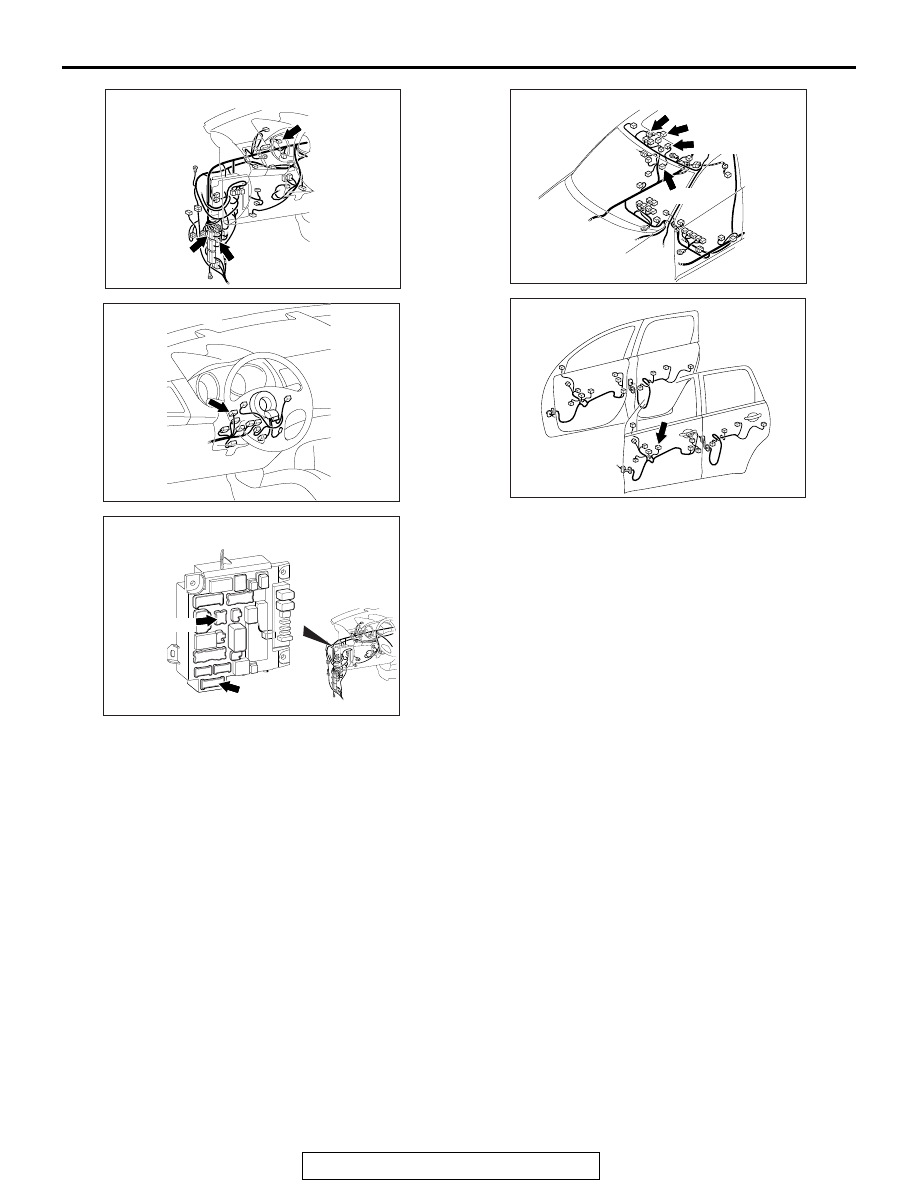
AC901075BJ

Connectors: C-34, C-40, C-127

C-34 (BR)

C-40

C-127 (BR)

AC702922 AE

Connector: C-212

ACA02655AS

Connectors: C-301, C-316

C-301

C-316

AC901079 BA

Connectors: D-04, D-39, D-135, D-136

D-135

D-136 (B)

D-04 (GR)

D-39

AC703415AD

Connector: E-19

TROUBLESHOOTING

TSB Revision

LOCAL INTERCONNECT NETWORK (LIN)

54B-42

STEP 1. Check the following connectors.
Check the following connectors:

• Column switch connector C-212

• ETACS-ECU connectors C-301 and C-316

• Sunroof motor assembly connector D-04 <Vehicles with 

sunroof>

• Lighting control sensor connector D-39 <Vehicles with auto 

light function>

• Power window main switch connector E-19

• Theft-alarm sensor connector D-136 <vehicles with 

theft-alarm sensor>

• Theft-alarm siren connector A-62 <vehicles with theft-alarm 

sensor>

• LIN cutoff control unit connector C-40 <vehicles with 

theft-alarm sensor>

Q: Are all the connectors in good condition?

YES : Go to Step 2.
NO :  Repair or replace the damaged component(s). Refer 

to GROUP 00E, Harness Connector Inspection 

P.00E-2

.

STEP 2. Check the LIN cutoff control unit.
Remove the LIN cutoff control unit. Check for continuity 
between the following terminals and inspect the relay.

• Continuity check

• Relay check

Q: Is the LIN cutoff control unit in good condition?

YES : Go to Step 3.
NO :  Replace the LIN cutoff control unit

Terminal number

Measurement value

5 to 3

Continuity exists (2 

Ω or 

less)

System voltage

Terminal 
number

Normal 
condition

At no energization

5 to 7

No 
continuity

With current supply 
[terminal 1 (+), terminal 8 
(

−)]

Continuity 
exists (2 

Ω 

or less)

TROUBLESHOOTING

TSB Revision

LOCAL INTERCONNECT NETWORK (LIN)

54B-43

STEP 3. Check the following wiring harness.
Check the wiring harness for open circuit between the following 
connectors:

• Wiring harness from ETACS-ECU connector C-301 (termi-

nal 1) to column switch connector C-212 (terminal 3)

• Wiring harness from ETACS-ECU connector C-316 (termi-

nal 1) to lighting control sensor connector D-39 (terminal 3) 
<Vehicles with auto light function>

• Wiring harness from ETACS-ECU connector C-316 (termi-

nal 1) to sunroof motor assembly connector D-04 (terminal 
7) <Vehicles with sunroof>

• Wiring harness from ETACS-ECU connector C-301 (termi-

nal 1) to power window main switch connector E-19 (termi-
nal 7)

• Wiring harness from ETACS-ECU connector C-316 (termi-

nal 1) to D-136 theft-alarm sensor connector D-136 (termi-
nal 2). <vehicles with theft-alarm sensor>

• Wiring harness from ETACS-ECU connector C-301 (termi-

nal 1) to A-62 theft-alarm siren connector A-62 (terminal 3). 
<vehicles with theft-alarm sensor>

NOTE: Also check intermediate connector A-03, C-34, C-127 
and D-135 for loose, corroded, or damaged terminals, or termi-
nals pushed back in the connector. If intermediate connector 
A-03, C-34, C-127 and D-135 is damaged, repair or replace the 
connector as described in GROUP 00E, Harness Connector 
Inspection 

P.00E-2

.

Q: Are all the wiring harness wires in good condition?

YES : Go to Step 4.
NO :  The wiring harness may be damaged or the 

connector(s) may have loose, corroded or damaged 
terminals, or terminals pushed back in the connector. 
Repair the wiring harness as necessary.

STEP 4. Measure the voltage at the LIN bus lines.
Check the LIN bus lines for short to power supply.
(1) Disconnect all the ECU connectors which are connected to 

the LIN bus lines.

(2) Turn the ignition switch from "LOCK" (OFF) to "ON" position 

.

(3) Measure the voltage between column switch connector 

C-212 (terminal 3) and ground.

• The voltmeter needle does not swing.

NOTE: If the LIN bus lines are short to power supply, the 
voltmeter indicates a constant value.

AC702831AY

Connector C-212
(Harness side)

TROUBLESHOOTING

TSB Revision

LOCAL INTERCONNECT NETWORK (LIN)

54B-44

(4) Measure the voltage between sunroof motor assembly 

connector D-04 (terminal 7) and ground. <Vehicles with 
sunroof>

• The voltmeter needle does not swing.

NOTE: If the LIN bus lines are short to power supply, the 
voltmeter indicates a constant value.

(5) Measure the voltage between lighting control sensor 

connector D-39 (terminal 3) and ground. <Vehicles with 
auto light function>

• The voltmeter needle does not swing.

NOTE: If the LIN bus lines are short to power supply, the 
voltmeter indicates a constant value.

Q: Is the check result normal?

YES : Go to Step 5.
NO :  The wiring harness may be damaged or the 

connector(s) may have loose, corroded or damaged 
terminals, or terminals pushed back in the connector. 
Repair the wiring harness as necessary.

AC702831AZ

Connector D-04
(Harness side)

AC608254 FE

Connector D-39
(Harness side)


Content   ..  1260  1261  1262  1263   ..