Mitsubishi Outlander GS45X. Manual - part 1254


  Index      Mitsubishi     Mitsubishi Outlander GS45X - service repair manual


Search            


Content   ..  1252  1253  1254  1255   ..


Mitsubishi Outlander GS45X. Manual - part 1254


TROUBLESHOOTING

TSB Revision

LOCAL INTERCONNECT NETWORK (LIN)

54B-9

STEP 5. Check the wiring harness between ETACS-ECU 
connector C-316 (terminal 2) and sunroof motor assembly 
connector D-04 (terminal 6).

• Check the power supply line (battery supply) for open circuit 

and short circuit.

Q: Is the wiring harness between ETACS-ECU connector 

C-316 (terminal 2) and sunroof motor assembly 
connector D-04 (terminal 6) in good condition?
YES : 
No action is necessary and testing is complete.
NO :  The wiring harness may be damaged or the 

connector(s) may have loose, corroded or damaged 
terminals, or terminals pushed back in the connector. 
Repair the wiring harness as necessary.

STEP 6. Check the wiring harness between ETACS-ECU 
connector C-316 (terminal 1) and sunroof motor assembly 
connector D-04 (terminal 7).

• Check the communication line for open circuit.

Q: Is the wiring harness between ETACS-ECU connector 

C-316 (terminal 1) and sunroof motor assembly 
connector D-04 (terminal 7) in good condition?
YES : 
Go to Step 7.
NO :  The wiring harness may be damaged or the 

connector(s) may have loose, corroded or damaged 
terminals, or terminals pushed back in the connector. 
Repair the wiring harness as necessary. Go to Step 7.

STEP 7. Recheck for diagnostic trouble code.
Check again if the DTC is set to the ETACS-ECU.
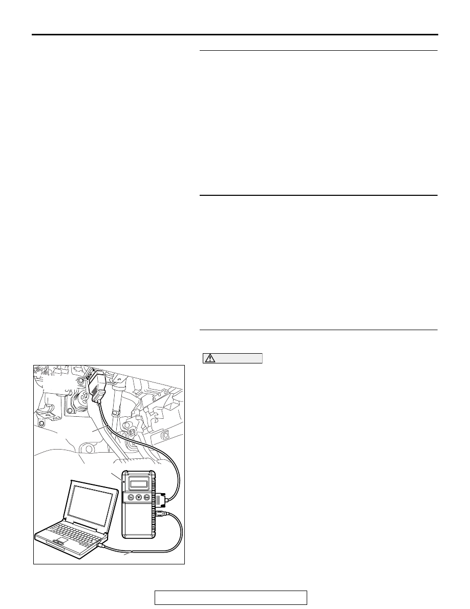
CAUTION

To prevent damage to scan tool MB991958, always turn the 
ignition switch to the "LOCK" (OFF) position before con-
necting or disconnecting scan tool MB991958.
(1) Ensure that the ignition switch is at the "LOCK" (OFF) 

position.

(2) Start up the personal computer.
(3) Connect special tool MB991827 to special tool MB991824 

and the personal computer.

(4) Connect special tool MB991910 to special tool MB991824.
(5) Connect special tool MB991910 to the data link connector.
(6) Erase the DTC.
(7) Turn the ignition switch to the "ON" position.
(8) Check if the DTC is set.
(9) Turn the ignition switch to the "LOCK" (OFF) position.
Q: Is the DTC set?

YES : Replace the sunroof motor assembly.
NO :  A poor connection, open circuit or other intermittent 

malfunction is present in the LIN bus lines between 
the sunroof motor assembly and the ETACS-ECU 
(Refer to GROUP 00, How to Cope with Intermittent 
Malfunction 

P.00-15

).

ZC501967

AC404789

AC702802

MB991824

MB991827

MB991910

Data link

connector

AB

TROUBLESHOOTING

TSB Revision

LOCAL INTERCONNECT NETWORK (LIN)

54B-10

DTC U0215: P/W SW (DR) LIN timeout

Power Window Main Switch LIN Communication Circuit

ETACS-
ECU

INTERFACE
CIRCUIT

LIN DRIVE
CIRCUIT

CPU

LIN DRIVE
CIRCUIT

POWER WINDOW
MAIN SWITCH

FUSE     

20

AC901075BG

Connectors: C-126, C-127

C-127 (BR)

C-126

ACA02655AO

Connectors: C-301, C-315

C-315

C-301

TROUBLESHOOTING

TSB Revision

LOCAL INTERCONNECT NETWORK (LIN)

54B-11

CAUTION

Before replacing the ECU, ensure that the com-
munication circuit is normal.

.

TROUBLE JUDGMENT

The ETACS-ECU receives signal from the power 
window main switch. If signal cannot be received at 
all, DTC U0215 will be set.

.

TECHNICAL DESCRIPTION (COMMENT)

Current trouble

• Connector(s) or wiring harness in the LIN bus 

lines between the power window main switch and 
the ETACS-ECU, the power supply system of the 
power window main switch, or the power window 
main switch itself may be defective.

Past trouble

• If DTC U0215 is stored as a past trouble, carry 

out diagnosis with particular emphasis on wiring 
and connector(s) in the LIN bus line between the 
power window main switch and the ETACS-ECU, 
and the power supply system of the power win-
dow main switch. For diagnosis procedures, refer 
to GROUP 00, How to Use Troubleshoot-
ing/Inspection Service Points 

− How to Treat Past 

Trouble 

P.00-17

.

.

TROUBLESHOOTING HINTS

• The power window main switch may be defective.

• The wiring harness or connectors may have 

loose, corroded, or damaged terminals, or termi-
nals pushed back in the connector.

DIAGNOSIS

Required Special Tools:

• MB991958: Scan Tool (M.U.T.-III Sub Assembly)

• MB991824: Vehicles Communication Interface (V.C.I.)

• MB991827: M.U.T.-III USB Cable

• MB991910: M.U.T.-III Main Harness A (Vehicles with 

CAN communication system)

STEP 1. Check ETACS-ECU connectors C-301 and C-315 
and power window main switch connector E-19 for loose, 
corroded or damaged terminals, or terminals pushed back 
in the connector.
Q: Are ETACS-ECU connectors C-301 and C-315 and power 

window main switch connector E-19 in good condition?
YES : 
Go to Step 2.
NO :  Repair or replace the damaged component(s). Go to 

Step 7.

AC703415AD

Connector: E-19

TROUBLESHOOTING

TSB Revision

LOCAL INTERCONNECT NETWORK (LIN)

54B-12

STEP 2. Check the ground circuit to the power window 
main switch. Measure the resistance at power window 
main switch connector E-19.
(1) Disconnect power window main switch connector E-19 and 

measure the resistance available at the wiring harness side 
of the connector.

(2) Measure the resistance value between power window main 

switch connector E-19 terminal 10 and ground.

• The resistance should be 2 ohms or less.

Q: Is the measured resistance 2 ohms or less?

YES : Go to Step 4.
NO :  Go to Step 3.

STEP 3. Check the wiring harness between power window 
main switch connector E-19 (terminal 10) and the ground.

• Check the ground wires for open circuit.

NOTE: Also check intermediate connector C-126 for loose, cor-
roded, or damaged terminals, or terminals pushed back in the 
connector. If intermediate connector C-126 is damaged, repair 
or replace the connector as described in GROUP 00E, Harness 
Connector Inspection 

P.00E-2

.

Q: Is the wiring harness between power window main 

switch connector E-19 (terminal 10) and the ground in 
good condition?
YES : 
No action is necessary and testing is complete.
NO :  The wiring harness may be damaged or the 

connector(s) may have loose, corroded or damaged 
terminals, or terminals pushed back in the connector. 
Repair the wiring harness as necessary.

STEP 4. Check the battery power supply circuit to the 
power window main switch. Measure the voltage at power 
window main switch connector E-19.
(1) Disconnect power window main switch connector E-19 

measure the voltage available at the wiring harness side of 
the connector.

(2) Measure the voltage between power window main switch 

connector E-19 terminal 10 and ground.

• The voltage should measure approximately 12 volts 

(battery positive voltage).

Q: Is the measured voltage approximately 12 volts (battery 

positive voltage)?
YES : 
Go to Step 6.
NO :  Go to Step 5.

AC608255 DF

Connector E-19
(Harness side)

AC608254 FA

Connector E-19
(Harness side)


Content   ..  1252  1253  1254  1255   ..