Mitsubishi Outlander GS45X. Manual - part 1243


  Index      Mitsubishi     Mitsubishi Outlander GS45X - service repair manual


Search            


Content   ..  1241  1242  1243  1244   ..


Mitsubishi Outlander GS45X. Manual - part 1243


CAMSHAFT

TSB Revision

ENGINE OVERHAUL <2.4L ENGINE>

11B-47

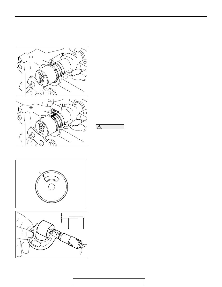
CAMSHAFT OIL CLEARANCE (PLASTIGAGE 
METHOD)

1. Thoroughly wipe oil on the outside diameter of the camshaft 

and the inside diameter of the bearing.

2. Install the bearing to the camshaft.
3. Put straightly the plastigage having the length of the bearing 

width on the journal axis, centering the axis.

4. Carefully install the bearing cap.Tighten the bolt as 

instructed in >>B<< Bolt Installation Point.

5. Remove the bolt and the bearing cap carefully.

6. Measure the plastigage whose width is most compressed 

using the scale printed on the plastigage bag. When the 
measured value deviates from the standard one, replace the 
bearing.

Standard value: 0 

 0.032 mm (0.0013 inch)

CAUTION

When the bearing is used again, be careful not to reverse 
the cylinder head side and the camshaft side at the instal-
lation.

.

VALVE TAPPET

1. Check the thickness stamp.

2. If the measured value in the table value is not in agreement 

with the value in the table to the thickness stamp, replace 
the valve tappet.
There are 47 kinds of valve tappets at intervals of 0.015 mm 
(0.0006 inch) in the range between 3.000 (0.1181 inch) and 
3.690 mm (0.1453 inch).

AK503390

Plastigage

AC

AK503391

Plastigage

AC

0

0

3

0

.

AK703500AF

Thickness stamp

Under view

AK304938

AB

Wall
thickness

CAMSHAFT

TSB Revision

ENGINE OVERHAUL <2.4L ENGINE>

11B-48

Thickness mm 
(in)

Thickness
stamp

Thickness mm 
(in)

Thickness
stamp

Thickness mm 
(in)

Thickness
stamp

3.000 (0.1181)

3.000

3.240 (0.1276)

3.240

3.480 (0.1370)

3.480

3.015 (0.1187)

3.015

3.255 (0.1281)

3.255

3.495 (0.1376)

3.495

3.030 (0.1193)

3.030

3.270 (0.1287)

3.270

3.510 (0.1382)

3.510

3.045 (0.1199)

3.045

3.285 (0.1293)

3.285

3.525 (0.1388)

3.525

3.060 (0.1205)

3.060

3.300 (0.1299)

3.300

3.540 (0.1394)

3.540

3.075 (0.1211)

3.075

3.315 (0.1305)

3.315

3.555 (0.1400)

3.555

3.090 (0.1217)

3.090

3.330 (0.1311)

3.330

3.570 (0.1406)

3.570

3.105 (0.1222)

3.105

3.345 (0.1317)

3.345

3.585 (0.1411)

3.585

3.120 (0.1228)

3.120

3.360 (0.1323)

3.360

3.600 (0.1417)

3.600

3.135 (0.1234)

3.135

3.375 (0.1329)

3.375

3.615 (0.1423)

3.615

3.150 (0.1240)

3.150

3.390 (0.1335)

3.390

3.630 (0.1429)

3.630

3.165 (0.1246)

3.165

3.405 (0.1341)

3.405

3.645 (0.1435)

3.645

3.180 (0.1252)

3.180

3.420 (0.1346)

3.420

3.660 (0.1441)

3.660

3.195 (0.1258)

3.195

3.435 (0.1352)

3.435

3.675 (0.1447)

3.675

3.210 (0.1264)

3.210

3.450 (0.1358)

3.450

3.690 (0.1453)

3.690

3.225 (0.1270)

3.225

3.465 (0.1364)

3.465

CYLINDER HEAD AND VALVES

TSB Revision

ENGINE OVERHAUL <2.4L ENGINE>

11B-49

CYLINDER HEAD AND VALVES

REMOVAL AND INSTALLATION

M1113006902965

AK703803

1

2

3

4

5

6

7

8

9

10

11

12

13

14

15

16

17

18

19

20

35 ± 2 N·m
26 ± 1 ft-lb

AC

21

Apply engine oil to
all moving parts
before installation.

 +90˚ +90˚

35 ± 2 N·m
26 ± 1 ft-lb 

 +90˚ +90˚

Removal steps 

>>D<<

1. Cylinder head bolt

>>D<<

2. Cylinder head bolt washer

>>D<<

3. Cylinder head bolt & washer 

assembly

>>C<<

4. Cylinder head assembly

>>C<

5. Cylinder head gasket
6. Engine oil control valve (OCV) filter

<<A>> >>B<<

7. Retainer lock
8. Valve spring retainer
9. Valve spring
10.Intake valve

<<A>> >>B<<

11. Retainer lock
12.Valve spring retainer
13.Valve spring
14.Exhaust valve

<<B>> >>A<<

15.Valve stem seal

<<B>> >>A<<

16.Valve stem seal
17.Intake valve guide
18.Exhaust valve guide
19.Intake valve seat
20.Exhaust valve seat
21.Cylinder head

Removal steps (Continued)

CYLINDER HEAD AND VALVES

TSB Revision

ENGINE OVERHAUL <2.4L ENGINE>

11B-50

Required Special Tool:

• MD998735: Valve spring compressor

• MB992089: Retainer holder

• MB992085: Valve stem seal pliers

REMOVAL SERVICE POINTS

.

<<A>> RETAINER LOCK REMOVAL

CAUTION

Be careful not to allow retainer holder C to interfere with 
the wall of the tappet hole and to damage it.
Use a special tool MD998735, and MB992089 to compress the 
valve spring and to remove the retainer lock.
NOTE: Store removed parts such as valves and springs with 
tags describing cylinder Number and installed position attached 
for reassembly.

.

<<B>> VALVE STEM SEAL REMOVAL

Use special tool MB992085 to firmly pinch the base (larger 
external shape) of the stem seal and twist it right and left for 
pulling out.

AK502741AD

MB992089

MD998735

AK502782AD

Valve stem seal

MB992085


Content   ..  1241  1242  1243  1244   ..