Mitsubishi Outlander GS45X. Manual - part 1230


  Index      Mitsubishi     Mitsubishi Outlander GS45X - service repair manual


Search            


Content   ..  1228  1229  1230  1231   ..


Mitsubishi Outlander GS45X. Manual - part 1230


CRANKSHAFT AND CYLINDER BLOCK

TSB Revision

ENGINE OVERHAUL <3.0L ENGINE>

11D-73

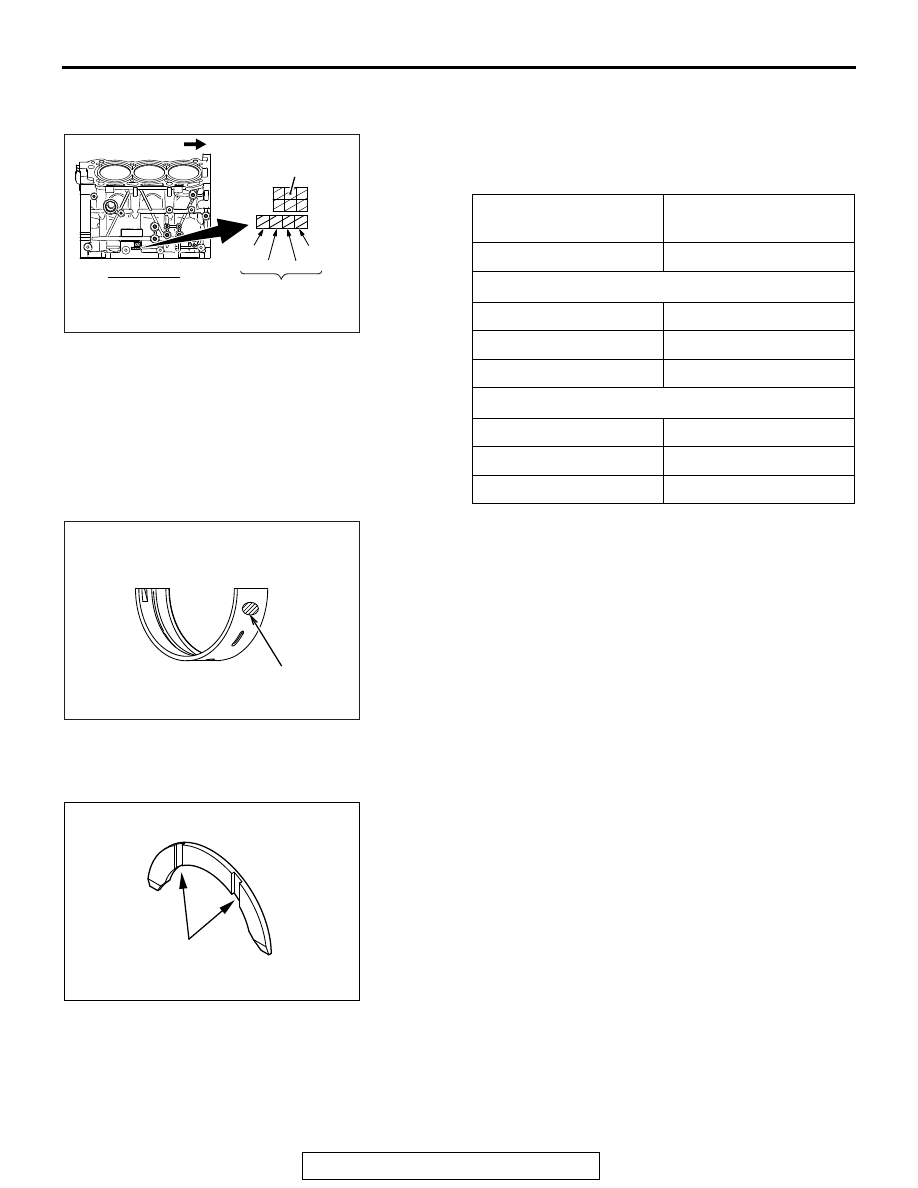
>>B<< CRANKSHAFT BEARING UPPER 
INSTALLATION

1. If the upper crankshaft bearing is replaced, select based on 

the identification mark of cylinder block (illustrated) and the 
table shown below.

2. The upper crankshaft bearing has the identification mark on 

the location shown in the illustration.

3. Install the upper selected crankshaft bearing.

.

>>C<< CRANKSHAFT THRUST BEARING 
INSTALLATION

1. Install the thrust bearing in the Number3 bearing bore in the 

cylinder block and in the bearing cap. For easier installation, 
apply engine oil to the bearings; this will help hold them in 
position.

2. The thrust bearings must be installed with their groove 

toward the crankshaft web.

.

Crankshaft journal 
(Upper)

Crankshaft bearing

Identification mark

Identification mark

Number 1 and 4 journal

1

1

2

2

3

3

Number 2 and 3 journal

0

0

1

1

2

2

AK600832

Right side

Timing belt side

Cylinder 
bore size

Crankshaft journal (Upper)
identification mark

No.4

No.3 No.2

No.1

AC

AK600833AC

Identification
mark

AK600798AC

Groove

CRANKSHAFT AND CYLINDER BLOCK

TSB Revision

ENGINE OVERHAUL <3.0L ENGINE>

11D-74

>>D<< CRANKSHAFT BEARING LOWER 
INSTALLATION

1. If the lower crankshaft bearing is replaced, select based on 

the identification mark of crankshaft (illustrated) and the 
table shown below.

2. The lower crankshaft bearing has the identification mark on 

the location shown in the illustration.

3. Install the lower selected crankshaft bearing.

.

>>E<< BEARING CAP / BEARING CAP BOLT 
INSTALLATION

1. Before installing the bearing cap bolt, check the bolt screw 

head is not damaged. If the screw head extremely gets 
damaged, replace it with a new bolt. The standard length of 
the new bolt measured from under the head is as follows:

Standard value: 91.2 

 92.2 mm (3.59  3.63 inches)

Crankshaft journal 
(Lower)

Crankshaft bearing

Identification mark

Identification mark

0

0

1

1

2

2

3

3

4

4

AK703264

No.1

No.2

No.3

No.4

AD

Crankshaft journal (Lower)
identification mark

Crankshaft pin
identification mark

Crankshaft
No.5 jornal

AK600834AC

Identification
mark

AK601719AC

Shank length

CRANKSHAFT AND CYLINDER BLOCK

TSB Revision

ENGINE OVERHAUL <3.0L ENGINE>

11D-75

2. Attach the bearing cap on the cylinder block as shown in the 

illustration.

3. Tighten the bearing cap bolts to specified torque in the 

sequence shown in the illustration.

Tightening torque: 24 

± 2 Nm (18 ± 1 ft-lb)

4. Make a paint mark on the head of each bolt.

CAUTION

• When the tightening angle is smaller than the specified 

tightening angle, the appropriate tightening capacity 
cannot be secured.

• When the tightening angle is larger than the specified 

tightening angle, remove the bolt to start from the 
beginning again according to the procedure.

5. Make a paint mark on the bearing cap 90 degrees from the 

paint mark made on the bolt, in the direction of tightening the 
bolt.

6. Turn each bolt 90 degrees in the tightening sequence 

specified in step 2, and make sure that the paint marks on 
the bolt and cap are aligned.

7. Check that the crankshaft rotates smoothly.
8. Check the end play. If it exceeds the limit value, replace the 

thrust bearing.

Standard value: 0.05 

 0.25 mm (0.002  0.009 inch)

Limit: 0.3 mm (0.01 inch)

AK600849

5

8

7

4

2

3

1

6

5

8

7

2

3

4

1

6

AC

Crankshaft

Front mark

Cylinder block

AK600850AC

Paint mark

Paint mark

90˚

AK700667

CRANKSHAFT AND CYLINDER BLOCK

TSB Revision

ENGINE OVERHAUL <3.0L ENGINE>

11D-76

.

>>F<< CRANKSHAFT REAR OIL SEAL 
INSTALLATION

Using special tools MB992075 and MB992183, press-fit a new 
crankshaft rear oil seal into the oil seal case.
NOTE: Put the edge position in place as shown in the illustra-
tion.

.

>>G<< OIL SEAL CASE INSTALLATION

1. Apply a 2.5 

± 0.5 mm (0.10 ± 0.01 inch) diameter bead of 

sealant (Three bond 1217G or exact equivalent) to the oil 
seal case.

2. Apply a small amount of engine oil to the entire 

circumference of the oil seal lip section, and place the oil 
seal case on the cylinder block.
NOTE: Install the oil seal case within 15 minutes after apply-
ing liquid gasket.
NOTE: Then wait at least one hour. Never start the engine 
or let engine oil or coolant touch the adhesion surface during 
that time.

.

>>H<< DRIVE PLATE BOLT INSTALLATION

1. Cleanly remove sealant, oil and dust on the drive plate bolt, 

the drive plate and the threaded portions of the crankshaft.

2. Apply oil to the drive plate and the seating surface of the 

drive plate bolt. 

3. Apply oil to the threaded hole of the crankshaft
4. Apply sealant (Three bond 1324 or  equivalent) to the thread 

portions of the drive plate bolt.

AK600829

MB992183

Oil seal case

MB992075

Edge

AC

AK600930AC

AK600847AE


Content   ..  1228  1229  1230  1231   ..