Mitsubishi Outlander GS45X. Manual - part 121
MMCS
TSB Revision
CHASSIS ELECTRICAL
54A-481
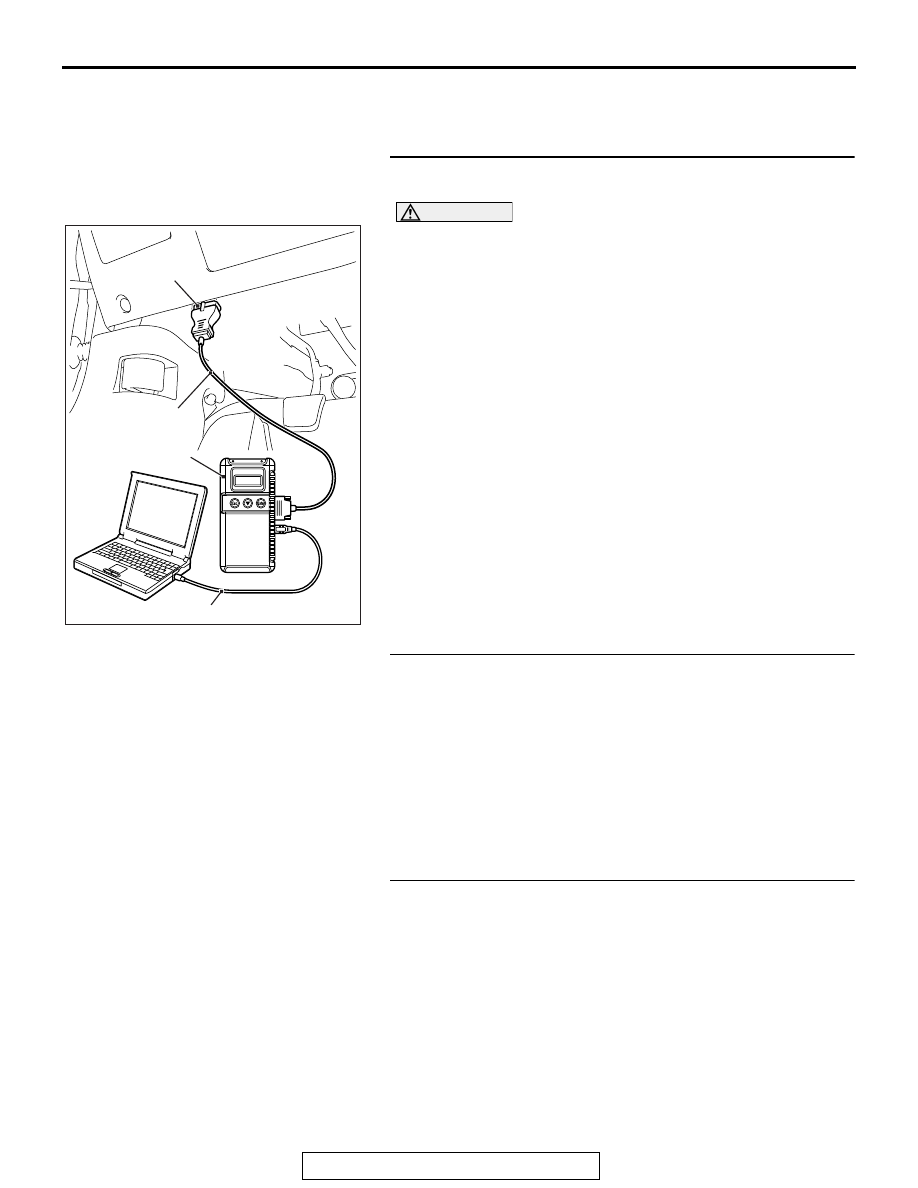
• MB991824: V.C.I.
• MB991827 M.U.T.-III USB Cable
• MB991910 M.U.T.-III Main Harness A
STEP 1. Using scan tool MB991958, diagnose the CAN bus
line
CAUTION
To prevent damage to scan tool MB991958, always turn the
ignition switch to the "LOCK" (OFF) position before con-
necting or disconnecting scan tool MB991958.
(1) Connect scan tool MB991958. Refer to "How to connect the
Scan Tool (M.U.T.-III)
."
(2) Turn the ignition switch to the "ON" position.
(3) Diagnose the CAN bus line.
(4) Turn the ignition switch to the "LOCK" (OFF) position.
Q: Is the CAN bus line found to be normal?
YES : Go to Step 2.
NO : Repair the CAN bus line. (Refer to GROUP 54C,
).
STEP 2. Using scan tool MB991958 read the satellite radio
tuner diagnostic trouble code.
Check whether a satellite radio tuner DTCs are set or not.
(1) Turn the ignition switch to the "ON" position.
(2) Check for satellite radio tuner DTCs.
(3) Turn the ignition switch to the "LOCK" (OFF) position.
Q: Is the DTC set?
YES : Diagnose the satellite radio tuner. (Refer to
.)
NO : Go to Step 3.
STEP 3. Using scan tool MB991958, read the SRS-ECU
diagnostic trouble code.
Check if the DTC U0195 is set to the SRS-ECU.
Q: Is the DTC set?
YES : Go to Step 4.
NO : Go to Step 5.
AC608435
Data link connector
MB991827
MB991824
MB991910
AB