Mitsubishi Outlander GS45X. Manual - part 119
MMCS
TSB Revision
CHASSIS ELECTRICAL
54A-473
DIAGNOSIS
Required Special Tools:
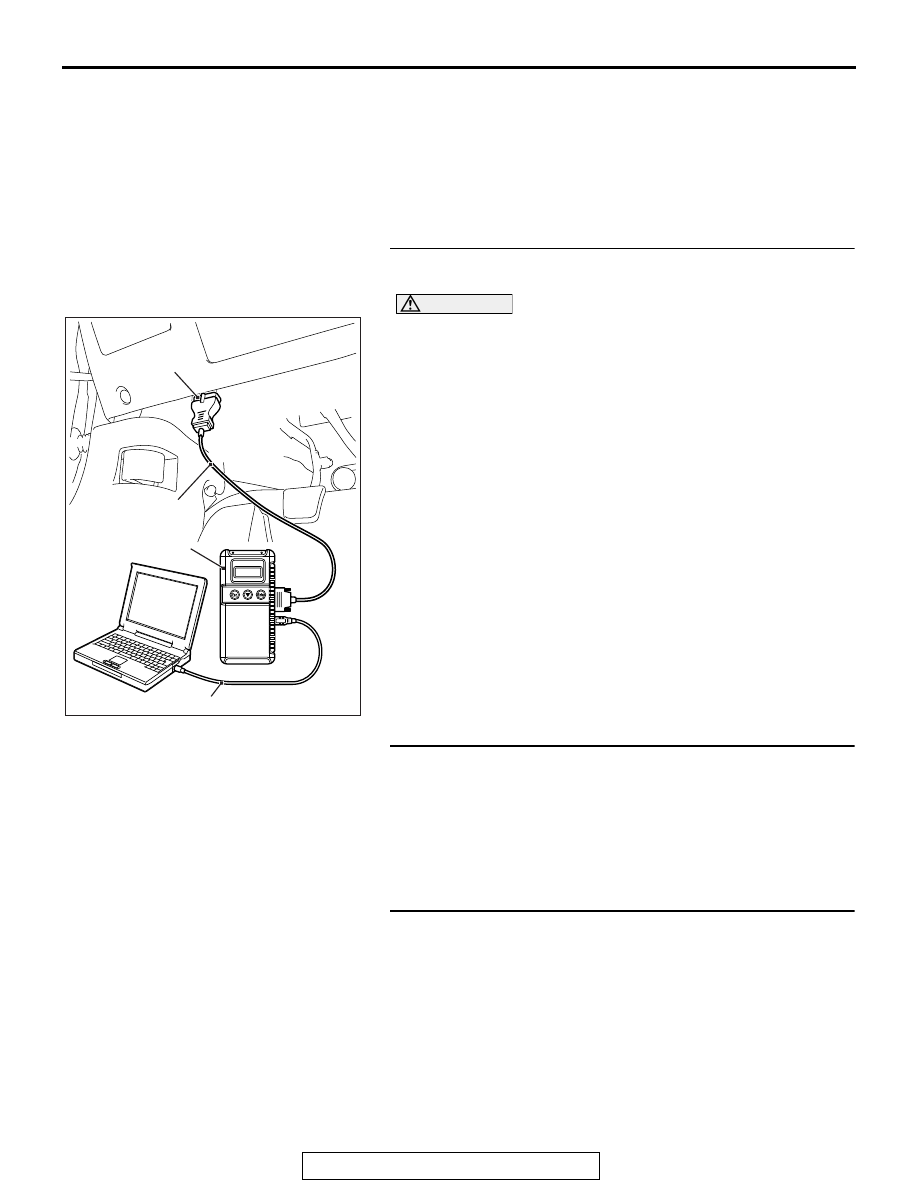
• MB991958 Scan Tool (M.U.T.-III Sub Assembly)
• MB991824: Vehicles Communication Interface (V.C.I.)
• MB991827 M.U.T.-III USB Cable
• MB991910 M.U.T.-III Main Harness A (Vehicles with
CAN communication system)
STEP 1. Using scan tool MB991958, diagnose the CAN bus
line.
CAUTION
To prevent damage to scan tool MB991958, always turn the
ignition switch to the "LOCK" (OFF) position before con-
necting or disconnecting scan tool MB991958.
(1) Connect scan tool MB991958. Refer to "How to connect the
Scan Tool (M.U.T.-III)
."
(2) Turn the ignition switch to the "ON" position.
(3) Diagnose the CAN bus line.
(4) Turn the ignition switch to the "LOCK" (OFF) position.
Q: Is the CAN bus line found to be normal?
YES : Go to Step 2.
NO : Repair the CAN bus line (Refer to GROUP 54C,
).
STEP 2. Using scan tool MB991958, read the occupant
classification-ECU diagnostic trouble code.
Check if DTC is set to the occupant classification-ECU.
Q: Is the DTC set?
YES : Troubleshoot the SRS (Refer to GROUP 52B,
).
NO : Go to Step 3.
STEP 3. Using scan tool MB991958, read the A/C-ECU
diagnostic trouble code.
Check if the DTC U0154 is set to the A/C-ECU.
Q: Is the DTC set?
YES : Go to Step 4.
NO : Go to Step 5.
AC608435
Data link connector
MB991827
MB991824
MB991910
AB