Mitsubishi Outlander GS45X. Manual - part 116


  Index      Mitsubishi     Mitsubishi Outlander GS45X - service repair manual


Search            


Content   ..  114  115  116  117   ..


Mitsubishi Outlander GS45X. Manual - part 116


MMCS

TSB Revision

CHASSIS ELECTRICAL

54A-461

DIAGNOSTIC TROUBLE CODE PROCEDURES

DTC B2226: AND [Audio visual Navigation (HDD) unit] error

CAUTION

• If DTC B2226 is set, be sure to diagnose the 

CAN bus line.

• When replacing the CAN box unit or multivi-

sion display, always check that the communi-
cation circuit is normal. (Check that the 
voltage is 10 V or more.)

.

TROUBLE JUDGMENT

When the CAN box unit receives the signal from the 
multivision display to indicate an abnormality 
occurred in the multivision display, the CAN box unit 
sets DTC B2226.

.

TROUBLESHOOTING HINT

• The CAN box unit may be defective

• The multivision display may be defective

DIAGNOSIS

Required Special Tools:

• MB991958: Scan Tool (M.U.T.-III Sub Assembly)

• MB991824: Vehicles Communication Interface (V.C.I.)

• MB991827: M.U.T.-III USB Cable

• MB991910: M.U.T.-III Main Harness A (Vehicles with 

CAN communication system)

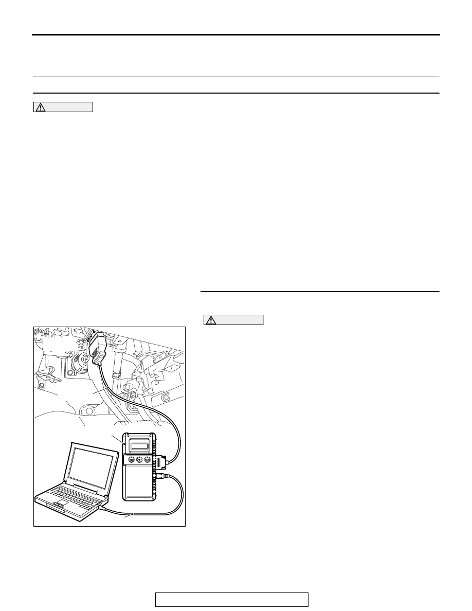
STEP 1. Using scan tool MB991958, diagnose the CAN bus 
line.

CAUTION

To prevent damage to scan tool MB991958, always turn the 
ignition switch to the "LOCK" (OFF) position before con-
necting or disconnecting scan tool MB991958.
(1) Connect scan tool MB991958. Refer to "How to connect the 

Scan Tool (M.U.T.-III) 

P.54A-458

."

(2) Turn the ignition switch to the "ON" position.
(3) Diagnose the CAN bus line.
(4) Turn the ignition switch to the "LOCK" (OFF) position.
Q: Is the CAN bus line found to be normal?

YES : Go to Step 2.
NO :  Repair the CAN bus line (Refer to GROUP 54C, 

Diagnosis 

P.54C-17

).

ZC501967

AC404789

AC702802

MB991824

MB991827

MB991910

Data link

connector

AB

MMCS

TSB Revision

CHASSIS ELECTRICAL

54A-462

STEP 2.Check that the multivision display operate.
Check that the FACTOR CODE is set to the service data log in 
the MMCS service mode "Versions Log Information." (Refer to 

P.54A-443

.)

Q: Is multivision display work normally?

YES : Go to Step 3.
NO :  Diagnose the multivision display (Refer to Trouble 

symptom chart 

P.54A-486

).

STEP 3. Recheck for diagnostic trouble code.
Check again if the DTC is set to the CAN box unit.
(1) Erase the DTC.
(2) Turn the ignition switch from "LOCK" (OFF) position to "ON" 

position.

(3) Check if DTC is set.
(4) Turn the ignition switch to the "LOCK" (OFF) position.
Q: Is the DTC set?

YES : Go to Step 4.
NO :  The trouble can be an intermittent malfunction (Refer 

to GROUP 00, How to use 
Troubleshooting/inspection Service Points 

− How to 

Cope with Intermittent Malfunction 

P.00-15

).

STEP 4. Recheck for diagnostic trouble code.
Temporarily replace the multivision display, and check if the 
DTC is set to the CAN box unit.
(1) Erase the DTC.
(2) Turn the ignition switch from "LOCK" (OFF) position to "ON" 

position.

(3) Check if DTC is set.
(4) Turn the ignition switch to the "LOCK" (OFF) position.
Q: Is the DTC set?

YES : Replace the CAN box unit.
NO :  Replace the multivision display.

MMCS

TSB Revision

CHASSIS ELECTRICAL

54A-463

DTC B2240: Communication error with CAN Box

CAUTION

• If DTC B2240 is set, be sure to diagnose the CAN bus line.
• When replacing the multivision display, always check that the communication circuit is normal. 

(Check that the voltage is 10 V or more.)

.

TROUBLE JUDGMENT

When the abnormality occurs in the transmis-
sion/reception data between the CAN box unit and 
multivision display, the CAN box unit sets DTC 
B2240.

.

PROBABLE CAUSES

• Multivision display may be malfunction

• CAN box unit may be malfunction

• Damaged wiring harness and connectors

DIAGNOSIS

Required Special Tools:

• MB991958 Scan Tool (M.U.T.-III Sub Assembly)

• MB991223: Harness Set

• MB992006: Extra Fine Probe

• MB991824: Vehicle Communication Interface (V.C.I.)

• MB991827 M.U.T.-III USB Cable

• MB991910 M.U.T.-III Main Harness A (Vehicles with 

CAN communication system)

CAN Box Unit Communication Circuit

MULTIVISION DISPLAY

CAN BOX UNIT

AC709494

AC

Connectors: C-07, C-13

C-07 (GR)

C-13

MMCS

TSB Revision

CHASSIS ELECTRICAL

54A-464

STEP 1. Perform "Network/Connect Line Check" of the 
MMCS service mode.
Perform "Network/Connect Line Check" of the MMCS service 
mode, and check that the communication between the CAN 
box unit and the multivision display is normal. (Refer to 

P.54A-443

.)

NOTE: The communication is not possible, "CAN BOX" is not 
displayed.
Q: Is "CAN BOX OK" displayed?

YES : Go to Step 2.
NO :  Go to Step 3.

STEP 2. Using scan tool MB991958, diagnose the CAN bus 
line.

CAUTION

To prevent damage to scan tool MB991958, always turn the 
ignition switch to the "LOCK" (OFF) position before con-
necting or disconnecting scan tool MB991958.
(1) Connect scan tool MB991958. Refer to "How to connect the 

Scan Tool (M.U.T.-III) 

P.54A-458

."

(2) Turn the ignition switch to the "ON" position.
(3) Diagnose the CAN bus line.
(4) Turn the ignition switch to the "LOCK" (OFF) position.
Q: Is the CAN bus line found to be normal?

YES : Intermittent malfunction is suspected. Refer to 

GROUP 00, How to Use Troubleshooting/Inspection 
Service Points 

− How to Cope with Intermittent 

Malfunction 

P.00-15

.

NO :  Repair the CAN bus line. (Refer to GROUP 54C, 

Diagnosis 

P.54C-17

).

STEP 3. Check CAN box unit connector C-13 and 
multivision display connector C-07 for loose, corroded or 
damaged terminals, or terminals pushed back in the 
connector.
Q: Are CAN box unit connector C-13 and multivision 

display connector C-07 in good condition?
YES : 
Go to Step 4.
NO :  Repair or replace the damaged component(s). Refer 

to GROUP 00E, Harness Connector Inspection 

P.00E-2

. The steering remote control switch should 

work normally.

ZC501967

AC404789

AC702802

MB991824

MB991827

MB991910

Data link

connector

AB


Content   ..  114  115  116  117   ..