Mitsubishi Outlander GS45X. Manual - part 1149


  Index      Mitsubishi     Mitsubishi Outlander GS45X - service repair manual


Search            


Content   ..  1147  1148  1149  1150   ..


Mitsubishi Outlander GS45X. Manual - part 1149


DIAGNOSIS

TSB Revision

KEYLESS OPERATION SYSTEM (KOS)

42B-175

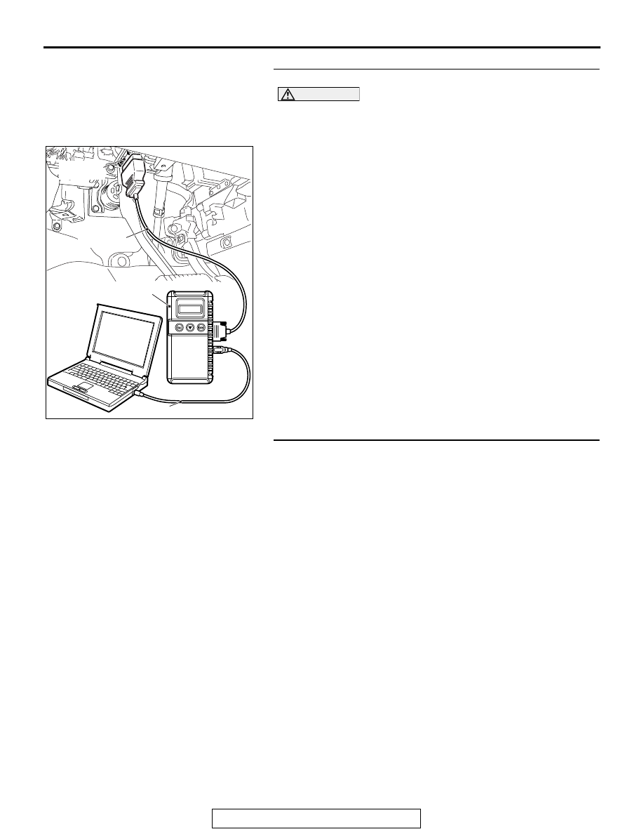
STEP 3. Using scan tool MB991958, read the actuator test.

CAUTION

To prevent damage to scan tool MB991958, always turn the 
ignition switch to the "LOCK" (OFF) position before con-
necting or disconnecting scan tool MB991958.
(1) Connect scan tool MB991958. Refer to "How to connect 

scan tool (M.U.T.-III) 

P.42B-13

."

(2) Turn the ignition switch to the "ON" position.
(3) Check that the outer tone alarm sounds (Refer to 

P.42B-185

).

(4) Turn the ignition switch to the "LOCK" (OFF) position.
Q: Is the DTC set?

YES : Go to Step 6.
NO :  Go to Step 4.

STEP 4. Check KOS-ECU connector C-102 and outer tone 
alarm connector F-13 for loose, corroded or damaged 
terminals, or terminals pushed back in the connector.
Q: Are KOS-ECU connector C-102 and outer tone alarm 

connector F-13 in good condition?
YES : 
Go to Step 5.
NO :  Repair or replace the damaged component(s). Refer 

to GROUP 00E, Harness Connector Inspection 

P.00E-2

. Check that the outer tone alarm works 

normally.

ZC501967

AC404789

AC701411AB

MB991824

MB991827

MB991910

Data link 
connector

DIAGNOSIS

TSB Revision

KEYLESS OPERATION SYSTEM (KOS)

42B-176

STEP 5. Check the wiring harness between KOS-ECU 
connector C-102 (terminal Nos. 35 and 37) and outer tone 
alarm connector F-13 (terminal Nos. 1 and 2). 

• Check the power supply and ground lines for open circuit.

NOTE: Also check intermediate connector C-32 and F-17 for 
loose, corroded, or damaged terminals, or terminals pushed 
back in the connector. If intermediate connector C-32 and F-17 
is damaged, repair or replace the damaged component(s) as 
described in GROUP 00E, Harness Connector Inspection 

P.00E-2

.

Q: Is the wiring harness between KOS-ECU connector 

C-102 (terminal Nos. 35 and 37) and outer tone alarm 
connector F-13 (terminal Nos. 1 and 2) in good 
condition?
YES : 
Go to Step 6.
NO :  The wiring harness may be damaged or the 

connector(s) may have loose, corroded or damaged 
terminals, or terminals pushed back in the connector. 
Repair the wiring harness as necessary. Check that 
the outer tone alarm works normally.

STEP 6. Check of the troubles
Check that the outer tone alarm sounds when the outer tone 
alarm sounding conditions are met.
Q: Is the check result normal?

YES : Intermittent malfunction is suspected. (Refer to 

GROUP 00, How to Use Troubleshooting/Inspection 
Service Points 

− How to cope with intermittent 

malfunctions 

P.00-15

).

NO :  Replace KOS-ECU and register the ID codes (Refer 

to 

P.42B-188

).

DIAGNOSIS

TSB Revision

KEYLESS OPERATION SYSTEM (KOS)

42B-177

Inspection Procedure 16: The keyless operation key cannot be registered using scan tool.

CAUTION

When replacing the ECU, always check that the 
communication circuit is normal.

.

TECHNICAL DESCRIPTION (COMMENT)

If only some keyless operation keys cannot be regis-
tered, the keyless operation key itself may be faulty. 
If no keyless operation key can be registered, the 
key assembly may have already been registered for 
another vehicle, or the KOS-ECU may be faulty.

.

TROUBLESHOOTING HINTS

• Insufficient inverse insertion of keyless operation 

key at the emergency operation

• Malfunction of the keyless operation key

• Damaged wiring harness and connectors

• Malfunction of receiver antenna module

• Malfunction of KOS-ECU

• Ignition key registered for other vehicle

DIAGNOSIS

Required Special Tools:

• MB991958: Scan Tool (M.U.T.-III Sub Assembly)

• MB991824: Vehicle Communication Interface (V.C.I.)

• MB991827: M.U.T.-III USB Cable

• MB991910: M.U.T.-III Main Harness A (Vehicles with 

CAN communication system)

ACA02752

IMMOBILIZER 
ANTENNA

KEYLESS
ENTRY
RECEIVER

Receiver Antenna  Module and KOS-ECU Circuit

KEYLESS 
OPERATION 
KEY

RECEIVER 
ANTENNA 
MODULE

KOS-ECU

TRANSPONDER

KEY ID

AB

AC702145AB

Connector: C-30, C-102

C-30

C-102

DIAGNOSIS

TSB Revision

KEYLESS OPERATION SYSTEM (KOS)

42B-178

STEP 1. Sufficiently insert the keyless operation key in the 
inverted direction at the emergency operation, and check 
the trouble symptom.
With the emergency operation by the sufficient inverse inser-
tion of keyless operation key, check if the key can be regis-
tered.
Q: Is the check result normal?

YES : The procedure is complete.
NO :  Go to Step 2.

STEP 2. Check the keyless operation key inserted in the 
key cylinder for interference.
Q: Are there other keyless operation keys or anything that 

interferes with the communication (things that generate 
radio waves such as magnets and an air-cleaning 
device that has a power plug) near the keyless 
operation key inserted in the key cylinder?
YES : 
Move away or remove other keyless operation keys 

or things that interfere with the communication (things 
that generate radio waves such as magnets and a 
air-cleaning device that has a power plug) near the 
keyless operation key. Then, go to step 3.

NO :  Go to Step 4.

STEP 3. Retest the system
Check that the keyless operation key can be registered.
Q: Is the keyless operation key that cannot be registered 

using scan tool?
YES : 
Go to Step 4.
NO :  The procedure is complete.

STEP 4. Check which keyless operation key cannot be 
registered.
Q: Can any one of the keyless operation keys be 

registered?
YES (Only some keys) : 
Replace the key that cannot be 

registered and register the ID codes (Refer to 

P.42B-188

). After registering the ID codes, go to Step 

6.

NO (All keys) : Go to Step 5.


Content   ..  1147  1148  1149  1150   ..