Mitsubishi Outlander GS45X. Manual - part 1066


  Index      Mitsubishi     Mitsubishi Outlander GS45X - service repair manual


Search            


Content   ..  1064  1065  1066  1067   ..


Mitsubishi Outlander GS45X. Manual - part 1066


DOOR

TSB Revision

BODY

42A-67

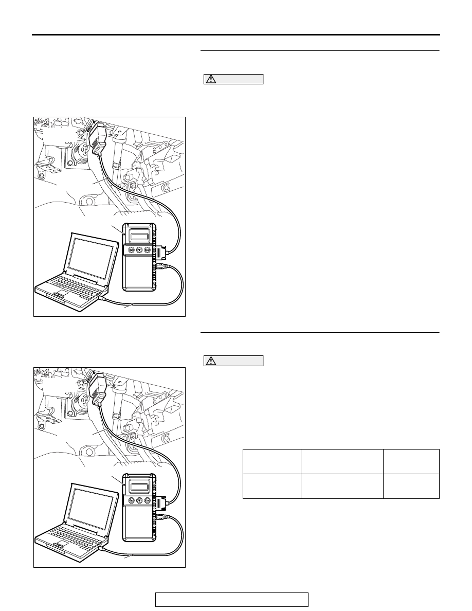
STEP 3. Using scan tool MB991958, read the ASC-ECU 
diagnostic trouble code.

CAUTION

To prevent damage to scan tool MB991958, always turn the 
ignition switch to the "LOCK" (OFF) position before con-
necting or disconnecting scan tool MB991958.
(1) Connect scan tool MB991958. Refer to GROUP 42B, "How 

to connect scan tool (M.U.T.-III) 

P.42B-13

."

(2) Turn the ignition switch to the "ON" position.
(3) Check that the ASC-ECU sets a diagnostic trouble code.
(4) Turn the ignition switch to the "LOCK" (OFF) position.
Q: Is the DTC set?

YES : Diagnose ASC-ECU (Refer to GROUP 35C, 

Diagnostic Trouble Code Chart 

P.35C-18

).

NO :  Go to Step 4.

STEP 4. Using scan tool MB991958, check data list.
Check the input signals from the liftgate lock release handle.

CAUTION

To prevent damage to scan tool MB991958, always turn the 
ignition switch to the "LOCK" (OFF) position before con-
necting or disconnecting scan tool MB991958.
(1) Connect scan tool MB991958. Refer to GROUP 42B, "How 

to connect scan tool (M.U.T.-III) 

P.42B-13

."

(2) Turn the ignition switch to the "ON" position.
(3) Check the data list of the ETACS.

• Liftgate lock release handle: from OFF to ON

(4) Turn the ignition switch to the "LOCK" (OFF) position.

OK: Normal condition is displayed.

Q: Is the check result normal?

YES : Go to Step 5.
NO :  Refer to 

P.42A-37

.

ZC501967

AC404789

AC701411AB

MB991824

MB991827

MB991910

Data link 
connector

Item No.

Item name

Normal 
condition

Item 230

Trunk / gate opener from OFF to 

ON

ZC501967

AC404789

AC701411AB

MB991824

MB991827

MB991910

Data link 
connector

DOOR

TSB Revision

BODY

42A-68

STEP 5. Check ETACS-ECU connector C-311 for loose, 
corroded or damaged terminals, or terminals pushed back 
in the connector.
Q: Is ETACS-ECU connector C-311 in good condition?

YES : Go to Step 6.
NO :  Repair or replace the damaged component(s). Refer 

to GROUP 00E, Harness Connector Inspection 

P.00E-2

. Verify that the liftgate can be locked and 

unlocked normally.

STEP 6. Check the liftgate lock actuator.
Remove the liftgate lock actuator. The illustration shows when 
the liftgate lock actuator is viewed from inside the liftgate. Refer 
to GROUP 42A, Liftgate Handle and Latch <Liftgate upper> 

P.42A-174

.

Q: Is the liftgate lock actuator normal?

YES : Go to Step 7.
NO :  Replace the liftgate lock actuator. Verify that the 

liftgate can be locked and unlocked normally.

STEP 7. Check the ground circuit to the liftgate lock 
actuator. Measure the resistance at liftgate lock actuator 
connector F-11.
(1) Disconnect liftgate lock actuator connector F-11 and 

measure the resistance on the wiring harness side of the 
connector.

(2) Measure the resistance value between terminal 2 and 

ground.

• The resistance should be 2 ohms or less.

Q: Is the measured resistance 2 ohms or less?

YES : Go to Step 9.
NO :  Go to Step 8.

Lever 
position

Battery 
connection

Lever operation

At the 
"SET" 
position

• Connect 

terminal 2 to 
negative battery 
terminal.

• Connect 

terminal 1 to 
positive battery 
terminal.

Lever moves 
from "SET" to 
"OPEN" position.

AC302760AG

Set

Lever

Open

AC702473

Connector F-11

AF

(harness side)

DOOR

TSB Revision

BODY

42A-69

STEP 8. Check the wiring harness between liftgate lock 
actuator connector F-11 (terminal 2) and ground.

• Check the power supply line for open circuit and short cir-

cuit.

Q: Is the wiring harness between liftgate lock actuator 

connector F-11 (terminal 2) and ground in good 
condition?
YES : 
No action is necessary and testing is complete.
NO :  The wiring harness may be damaged or the 

connector(s) may have loose, corroded or damaged 
terminals, or terminals pushed back in the connector. 
Repair the wiring harness as necessary. Verify that 
the liftgate can be locked and unlocked normally.

STEP 9. Check the wiring harness between ETACS-ECU 
connector C-311 (terminal 1) and liftgate lock actuator 
connector F-11 (terminal 1).

• Check the power supply line for open circuit and short cir-

cuit.

NOTE: Also check intermediate connector D-12 for loose, cor-
roded, or damaged terminals, or terminals pushed back in the 
connector. If intermediate connector D-12 is damaged, repair or 
replace the damaged component(s) as described in GROUP 
00E, Harness Connector Inspection 

P.00E-2

.

Q: Is the wiring harness between ETACS-ECU connector 

C-311 (terminal 1) and liftgate lock actuator connector 
F-11 (terminal 1) in good condition?
YES : 
Go to Step 10.
NO :  The wiring harness may be damaged or the 

connector(s) may have loose, corroded or damaged 
terminals, or terminals pushed back in the connector. 
Repair the wiring harness as necessary. Verify that 
the liftgate can be locked and unlocked normally.

STEP 10. Retest the system.
Check that the liftgate can be locked and unlocked normally.
Q: Is the check result normal?

YES : No action is necessary and testing is complete.
NO :  Replace the ETACS-ECU. Check that the liftgate can 

be locked and unlocked normally.

DOOR

TSB Revision

BODY

42A-70

INSPECTION PROCEDURE A-6: Selector "P" Position-linked Door Unlock Function does not Operate.

CAUTION

Before replacing the ECU, ensure that the power supply 
circuit, the ground circuit and the communication circuit 
are normal.

.

OPERATION

ETACS-ECU determines whether the shift position is 
"P" or not according to the shift position signal sent 
by transaxle control module.

.

TECHNICAL DESCRIPTION (COMMENT)

If the doors are not unlocked when the selector lever 
is shifted to the "P" position, a malfunction of the shift 
position signal input circuit(s) or ETACS-ECU is sus-
pected. Also, the selector "P" position-linked door 
unlock function may have been set to "Disabled" with 
the customization function.

.

TROUBLESHOOTING HINTS

• Malfunction of selector lever

• Malfunction of ETACS-ECU

• Damaged wiring harness and connectors

DIAGNOSTIC PROCEDURE

Required Special Tools:

• MB991223: Harness Set

• MB992006: Extra Fine Probe

•  MB991958: Scan Tool (M.U.T.-III Sub Assembly)

• MB991824: Vehicles Communication Interface (V.C.I.)

• MB991827: M.U.T.-III USB Cable

• MB991910: M.U.T.-III Main Harness A

STEP 1. Checking central door unlocking operation
Check that the central door locking system works normally.
Q: Is the check result normal?

YES : Go to Step 2.
NO :  Refer to 

P.42A-37

.

AC702939

Selector "P" Position-linked Door Unlock Function 

ETACS-ECU

(CAN_L line)

CAN Communication line
(CAN_H line)

Input signal

AD

CAN Communication line

Transaxle control 
module

Transmission range switch ("P" position)


Content   ..  1064  1065  1066  1067   ..