Mitsubishi Outlander GS45X. Manual - part 1036


  Index      Mitsubishi     Mitsubishi Outlander GS45X - service repair manual


Search            


Content   ..  1034  1035  1036  1037   ..


Mitsubishi Outlander GS45X. Manual - part 1036


HOW TO DIAGNOSE

TSB Revision

GENERAL <ELECTRICAL>

00E-9

5. Ohmmeter

An ohmmeter is used to check continuity or measure 
resistance of a switch or coil. If the measuring range has 
been changed, the zero point must be adjusted before 
measurement.

CHECKING FUSES

M1001005000141

A blade type fuse has test taps provided to allow checking of 
the fuse itself without removing it from the fuse block. The fuse 
is okay if the test light comes on when its one lead is connected 
to the test taps (one at a time) and the other lead is grounded. 
Remember to turn the ignition switch to ON to ensure all cir-
cuits are live.

CAUTIONS IN EVENT OF BLOWN FUSE

When a fuse is blown, there are two probable causes. One is 
that it is blown due to flow of current exceeding its rating. The 
other is that it is blown due to repeated on/off current flowing 
through it. Which of the two causes is responsible can be easily 
determined by visual check as described below.
1. Fuse blown due to current exceeding rating

The illustration shows the state of a fuse blown due to this 
cause. In this case, do not replace the fuse with a new one 
hastily since a current heavy enough to blow the fuse has 
flowed through it. First, check the circuit for shorts and check 
for abnormal electric parts. After correcting shorts or 
replacing parts, use only a fuse of the same capacity as a 
replacement. Never use a fuse of larger capacity than the 
original fuse. If a larger capacity fuse is used, electric parts 
or wiring could be damaged, or could start a fire.

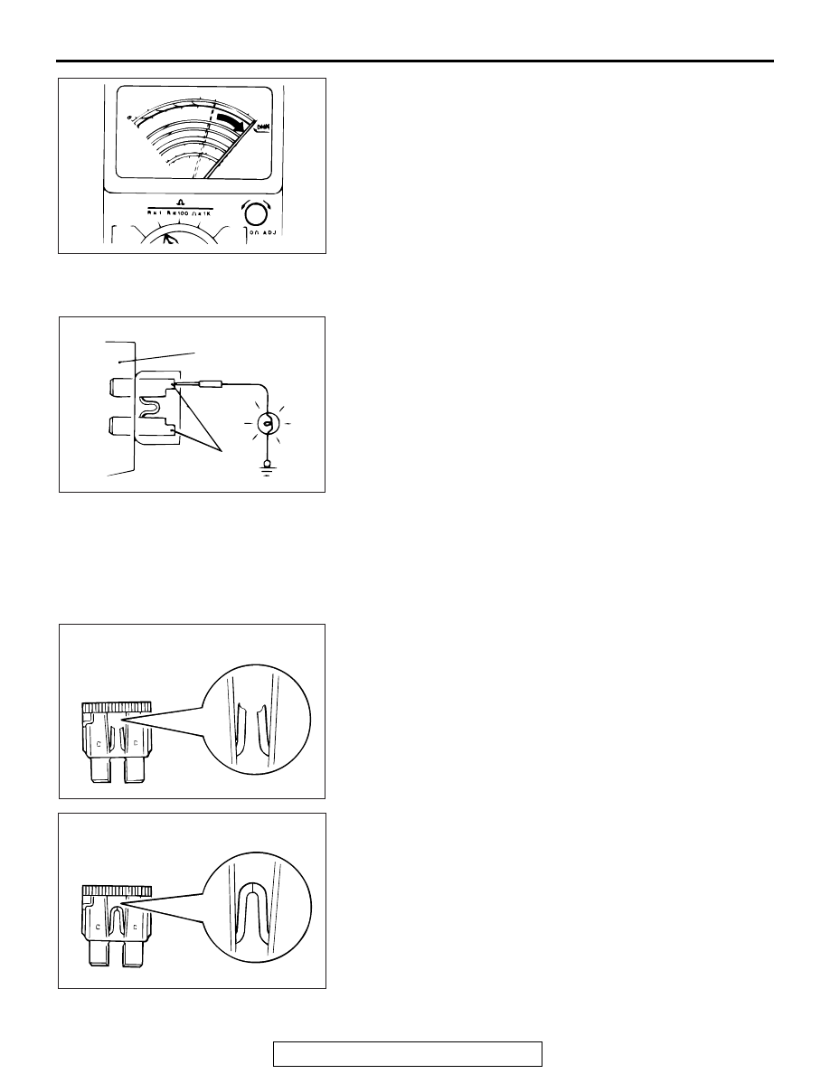
2. Fuse blown due to repeated turning current on and off

The illustration shows the state of a fuse blown due to 
repeated current on/off. Normally, this type of problem 
occurs after a fairly long period of use and is less frequent 
than above. In this case, simply replace with a new fuse of 
the same capacity.

ACX00943

ACX00951AB

FUSE BLOCK

TEST TAPS

ACX00952 AB

STATE OF FUSE BLOWN DUE TO
OVERCURRENT

ACX00953 AB

STATE OF FUSE BLOWN DUE TO
THERMAL FATIGUE

HOW TO DIAGNOSE

TSB Revision

GENERAL <ELECTRICAL>

00E-10

CHECKING SWITCHES

M1001004800177

In a circuit diagram, a switch is shown in the idle state.
1. Normally open or normally closed switch

Switches are classified into those which open the circuit and 
those which close the circuit when off.
Switches are shown in their normal state unless specified 
otherwise.

2. Switch connection

This figure illustrates a complex switch. The continuity 
between terminals at each position is as indicated in the 
table below.

SWITCH 
POSITION

TESTER 
CONNECTION

SPECIFIED 
CONDITION

OFF

1st stage

1

−5−6

Continuity

2nd stage

1

−4−6

Continuity

3rd stage

1

−3−6

Continuity

4th stage

1

−2−6

Continuity

ACX00944AC

CURRENT
FLOWS

CURRENT DOES
NOT FLOW

CURRENT DOES
NOT FLOW

CURRENT FLOWS

OFF

OFF

ON

ON

NORMALLY OPEN (NO) TYPE

NORMALLY CLOSED (NC) TYPE

ACX00945 AB

6

OFF

5

4

3

2

1

1ST 2ND 3RD 4TH STAGE

HOW TO DIAGNOSE

TSB Revision

GENERAL <ELECTRICAL>

00E-11

CHECKING RELAYS

M1001004900152

1. By using a relay, a heavy current can be turned on and off by 

a switch using much less current. For example, in the circuit 
shown here, when the switch is turned on (closed), current 
flows to the coil of the relay. Then, its contact is turned on 
(closed) and the light comes on. The current flowing through 
the switch is much less than that for the light.

2. When current flows through the coil of a relay, its core is 

magnetized to attract the iron piece, closing (ON) the 
contact at the tip of the iron piece. When the coil current is 
turned off, the iron piece returns to its original position by a 
spring, opening the contact (OFF).

3. Relays may be classified as the normally open-type or the 

normally closed-type, depending on their contact 
construction.
NOTE: The deenergized state means that no current is flow-
ing through the coil. The energized state means that current 
is flowing through the coil.

(1) The normally open-type

When a normally open relay as illustrated here is 
checked, there should be no continuity between terminals 
3 and 4 when the relay is deenergized. There should be 
continuity between terminals 3 and 4 when battery 
voltage and ground are applied to terminals 1 and 2. The 
relay condition is determined by this check.
NOTE: Check the relay in both situation which is ener-
gized and is not energized.

(2) The normally closed-type

When a normally closed relay as illustrated here is 
checked, there should be continuity between terminals 3 
and 4 when the relay is deenergized. There should be no 
continuity between terminals 3 and 4 when battery 
voltage and ground are applied to terminals 1 and 2. The 
relay condition is determined by this check.
NOTE: Check the relay in both situation which is ener-
gized and is not energized.

ACX00948 AB

POWER SUPPLY

FUSE

LIGHT

RELAY

SWITCH
ON

OFF

ON

OFF

AC308621 AB

COVER

SPRING

IRON
CORE

COIL

IRON
PIECE

CONTACT

NORMALLY OPEN (NO) TYPE

ENERGIZED STATE

AC310636 AB

NORMALLY OPEN (NO) TYPE

DEENERGIZED STATE ENERGIZED STATE

CURRENT FLOWS

CURRENT DOES
NOT FLOW

4

3

2

1

4

3

2

1

AC310637 AB

4

3

2

1

4

3

2

1

NORMALLY CLOSED (NC) TYPE

DEENERGIZED STATE ENERGIZED STATE

CURRENT FLOWS

CURRENT DOES
NOT FLOW

HOW TO DIAGNOSE

TSB Revision

GENERAL <ELECTRICAL>

00E-12

CABLES AND WIRES CHECK

M1001005100041

1. Check connections for looseness, rust, and stains.
2. Check terminals and wires for corrosion.
3. Check terminals and wires for open circuit or impending 

open circuit.

4. Check wire insulation and coating for damage, cracks, and 

wear.

5. Check conductive parts of terminals for contact with other 

metallic parts (vehicle body and other parts).

6. Check grounding parts to verify that there is complete 

continuity between attaching bolt(s) and vehicle body.

7. Check for incorrect wiring.
8. Check that harnesses are secured to prevent contact with 

sharp edges and corners or hot parts (exhaust manifold, 
pipe, etc.).

9. Check that harnesses are secured firmly to provide enough 

clearance from the fan pulley, fan belt, and other rotating or 
moving parts.

10.Check that the harnesses between fixed parts (such as the 

vehicle body) and vibrating parts (such as the engine) are 
long enough to allow for vibration and movement.

BATTERY HANDLING

M1001005200048

WARNING

Battery posts, terminals and related accessories con-
tain lead and lead compounds. WASH HANDS AFTER 
HANDLING.

When checking or servicing does not require power from the 
vehicle battery, be sure to disconnect the cable from the battery 
(

−) terminal. This will prevent problems that could be caused by 

a short circuit. Disconnect the (

−) battery terminal first and 

reconnect it last.

ACX00954 AB

ACX00955AB

AC000017


Content   ..  1034  1035  1036  1037   ..