Mitsubishi Outlander GS45X. Manual - part 1001


  Index      Mitsubishi     Mitsubishi Outlander GS45X - service repair manual


Search            


Content   ..  999  1000  1001  1002   ..


Mitsubishi Outlander GS45X. Manual - part 1001


MANUAL A/C DIAGNOSIS

TSB Revision

HEATER, AIR CONDITIONING AND VENTILATION

55A-31

STEP 4. Check the wiring harness between ambient air 
temperature sensor connector A-44 (terminals 2 and 1) and 
ETACS-ECU connector C-312 (terminals 7 and 14).

• Check the sensor signal line and ground line for open and 

short circuit.

Q: Is the wiring harness between ambient air temperature 

sensor connector A-44 (terminals 2 and 1) and 
ETACS-ECU connector C-312 (terminals 7 and 14) in 
good condition?
YES : 
Go to Step 5.
NO :  Repair the wiring harness.

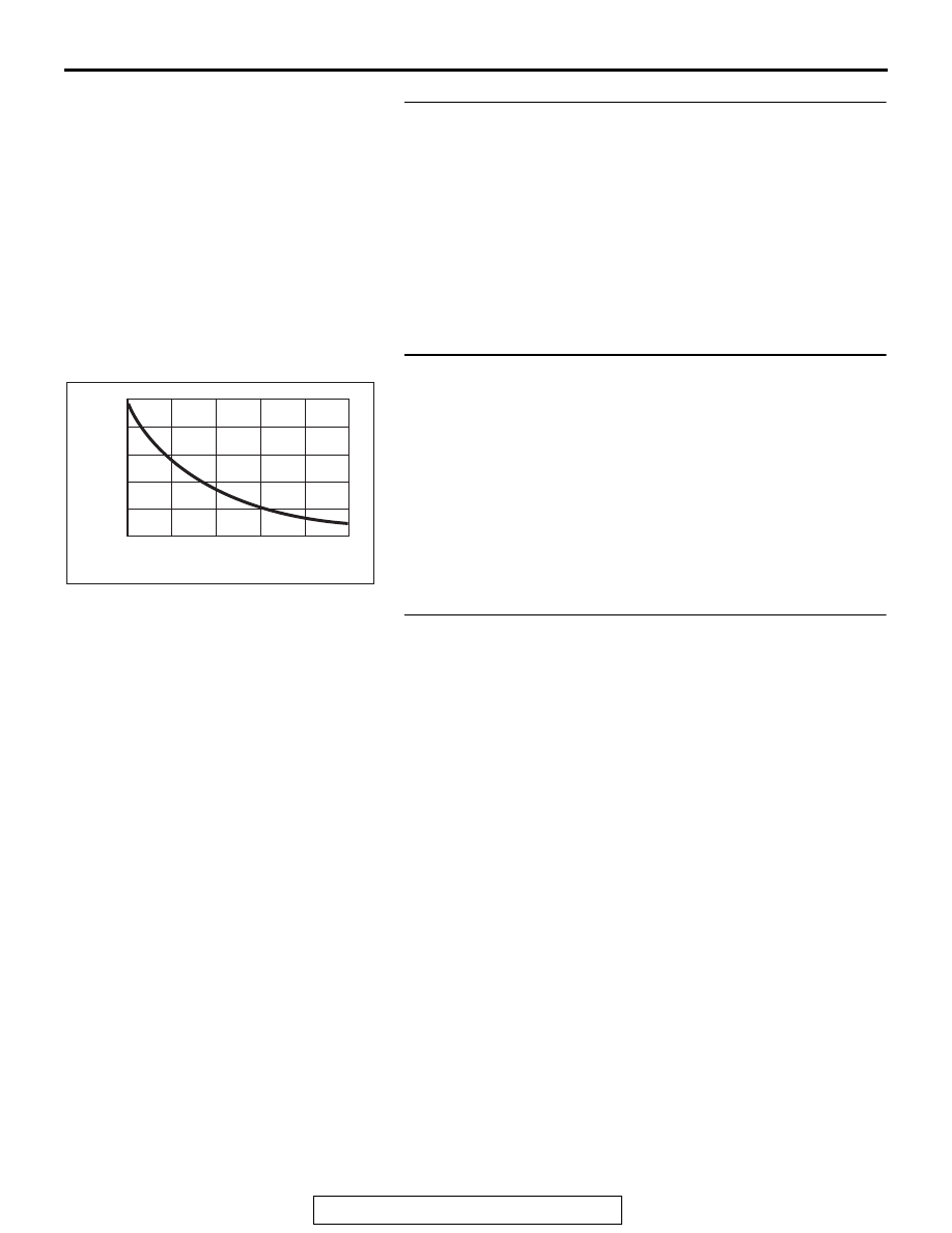
STEP 5. Check the ambient air temperature sensor.
Measure the resistance between connector terminals 1 and 2 
under at least two different temperatures. The resistance val-
ues should generally match those in the graph. 
NOTE: The temperature at the check should not exceed the 
range in the graph. 
Q: Is the ambient air temperature sensor in good 

condition?
YES : 
Replace the A/C-ECU. Then go to Step 6.
NO :  Replace the ambient air temperature sensor. Then go 

to Step 6.

STEP 6. Recheck for diagnostic trouble code.
Check again if the DTC is set.
(1) Connect scan tool MB991958 to the data link connector
(2) Turn the ignition switch to the "ON" position.
(3) Check if the DTC is set.
(4) Turn the ignition switch to the "LOCK" (OFF) position.
Q: Is the check result satisfactory?

YES : The procedure is complete.
NO :  Return to Step 1.

AC209192

10

8

6

4

2

0

AB

10
(50)

30
(86)

Resistance

(k

Ω)

Temperature ºC (ºF)

  0
(32)

  40
(104)

-10
(14)

 20
(68)

MANUAL A/C DIAGNOSIS

TSB Revision

HEATER, AIR CONDITIONING AND VENTILATION

55A-32

DTC B1079: Refrigerant Leaks

.

DTC SET CONDITION

DTC B1079 will be set when the A/C pressure sen-
sor detects the refrigerant pressure of specified level 
or less.
NOTE: When DTC B1079 is set, the A/C indicator of 
A/C control panel flashes.

.

TECHNICAL DESCRIPTION (COMMENT)

Current trouble

• The refrigerant amount is not at the specified 

level, or the wiring harness or connector between 
the A/C-ECU and A/C pressure sensor, and the 
A/C-ECU itself or A/C pressure sensor itself may 
be failed.

AC702371

A/C-ECU

AB

A/C Pressure Sensor Circuit

A/C PRESSURE 
SENSOR

AC702372AB

Connector: A-50

A-50 (B)

AC702208AH

Connector: C-109

C-109 (B)

MANUAL A/C DIAGNOSIS

TSB Revision

HEATER, AIR CONDITIONING AND VENTILATION

55A-33

Past trouble

• If DTC B1079 is stored as a past trouble, carry 

out diagnosis with particular emphasis on wiring 
and connector(s) between the A/C-ECU and the 
A/C pressure sensor. If the connectors and wiring 
are normal, and obviously the ECU is the cause 
of the trouble, replace the ECU. If in doubt, do not 
replace the ECU.

.

TROUBLESHOOTING HINT

• Malfunction of connector.

• Malfunction of the harness.

• Malfunction of the A/C pressure sensor.

• Malfunction of the A/C-ECU.

DIAGNOSIS

Required Special Tool:

•  MB991958: Scan Tool (M.U.T.-III Sub Assembly)

• MB991824: Vehicle Communication Interface (V.C.I.)

• MB991827: M.U.T.-III USB Cable

• MB991910: M.U.T.-III Main Harness A (Vehicles with 

CAN communication system)

STEP 1. Using scan tool MB991958, diagnose the CAN bus 
line

CAUTION

To prevent damage to scan tool MB991958, always turn the 
ignition switch to the "LOCK" (OFF) position before con-
necting or disconnecting scan tool MB991958.
(1) Connect scan tool MB991958. Refer to "How to connect the 

Scan Tool (M.U.T.-III) 

P.55A-7

."

(2) Turn the ignition switch to the "ON" position.
(3) Diagnose the CAN bus line.
(4) Turn the ignition switch to the "LOCK" (OFF) position.
Q: Is the CAN bus line found to be normal?

YES : Go to Step 2.
NO :  Repair the CAN bus line. (Refer to GROUP 54C, 

Diagnosis 

P.54C-17

).

STEP 2. Recheck for diagnostic trouble code.
Recheck if the DTC is set.
(1) Erase the DTC.
(2) Turn the ignition switch to "ON" position.
(3) Check if the DTC is set.
Q: Is the check result satisfactory?

YES : It can be assumed that this malfunction is intermittent. 

Refer to GROUP 00, How to Use 
Troubleshooting/Inspection Service Points 

− How to 

Cope with Intermittent Malfunctions 

P.00-15

.

NO :  Go to Step 3. 

ZC501967

AC404789

AC701411AB

MB991824

MB991827

MB991910

Data link 
connector

MANUAL A/C DIAGNOSIS

TSB Revision

HEATER, AIR CONDITIONING AND VENTILATION

55A-34

STEP 3. Check A/C pressure sensor connector A-50 and 
A/C-ECU connector C-109 for loose, corroded or damaged 
terminals, or terminals pushed back in the connector.
Q: Are air A/C pressure sensor connector A-50 and 

A/C-ECU connector C-109 in good condition?
YES : 
Go to Step 4.
NO :  Repair or replace the connector. Refer to GROUP 

00E, Harness Connector Inspection 

P.00E-2

.

STEP 4. Check the wiring harness between A/C-ECU 
connector C-109 (terminals 20, 16 and 19) and A/C 
pressure sensor connector A-50 (terminals 3, 2 and 1).
NOTE: Also check intermediate connectors C-33 for loose, cor-
roded, or damaged terminals, or terminals pushed back in the 
connector. If intermediate connector C-33 is damaged, repair or 
replace the connector as described in GROUP 00E, Harness 
Connector Inspection 

P.00E-2

.

• Check the sensor signal line and ground line for open and 

short circuit.

Q: Is the wiring harness between A/C-ECU connector 

C-109 (terminals 20, 16 and 19) and A/C pressure sensor 
connector A-50 (terminals 3, 2 and 1) in good condition?
YES : 
Go to Step 5.
NO :  Repair the wiring harness.


Content   ..  999  1000  1001  1002   ..