Content .. 998 999 1000 1001 ..
Mitsubishi Outlander GS45X. Manual - part 1000
MANUAL A/C DIAGNOSIS
TSB Revision
HEATER, AIR CONDITIONING AND VENTILATION
55A-27
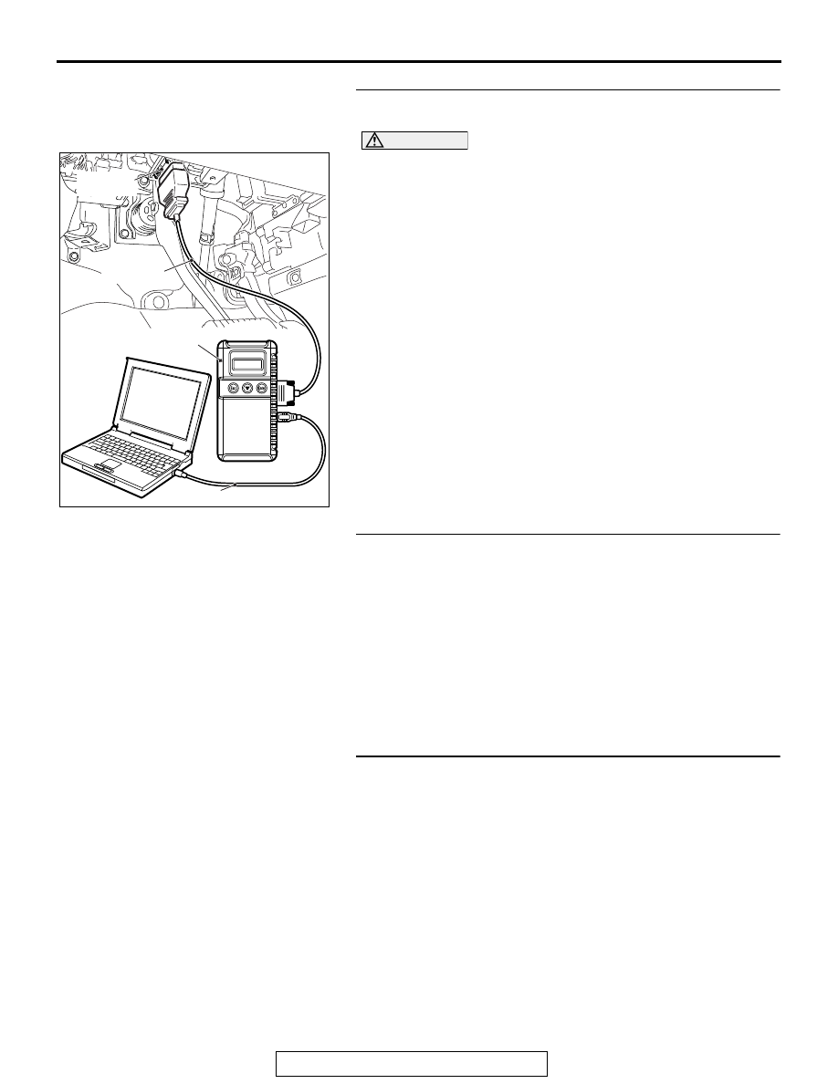
STEP 1. Using scan tool MB991958, diagnose the CAN bus
line
CAUTION
To prevent damage to scan tool MB991958, always turn the
ignition switch to the "LOCK" (OFF) position before con-
necting or disconnecting scan tool MB991958.
(1) Connect scan tool MB991958. Refer to "How to connect the
Scan Tool (M.U.T.-III)
(2) Turn the ignition switch to the "ON" position.
(3) Diagnose the CAN bus line.
(4) Turn the ignition switch to the "LOCK" (OFF) position.
Q: Is the CAN bus line found to be normal?
YES : Go to Step 2.
NO : Repair the CAN bus line. (Refer to GROUP 54C,
).
STEP 2. Recheck for diagnostic trouble code.
Recheck if the DTC is set.
(1) Erase the DTC.
(2) Turn the ignition switch to "ON" position.
(3) Check if the DTC is set.
Q: Is the check result satisfactory?
YES : It can be assumed that this malfunction is intermittent.
Refer to GROUP 00, How to Use
Troubleshooting/Inspection Service Points
− How to
Cope with Intermittent Malfunctions
.
NO : Go to Step 3.
STEP 3. Check air thermo sensor connector C-118 and
A/C-ECU connector C-108 for loose, corroded or damaged
terminals, or terminals pushed back in the connector.
Q: Are air thermo sensor connector C-118 and A/C-ECU
connector C-108 in good condition?
YES : Go to Step 4.
NO : Repair or replace the connector. Refer to GROUP
00E, Harness Connector Inspection
ZC501967
AC404789
AC701411AB
MB991824
MB991827
MB991910
Data link
connector