Mitsubishi Outlander GS45X. Manual - part 90


  Index      Mitsubishi     Mitsubishi Outlander GS45X - service repair manual


Search            


Content   ..  88  89  90  91   ..


Mitsubishi Outlander GS45X. Manual - part 90


RADIO AND CD PLAYER

TSB Revision

CHASSIS ELECTRICAL

54A-357

Code No.B2450 Switch panel communication

CAUTION

If there is any problem in the CAN bus lines, an 
incorrect diagnostic trouble code may be set. 
Prior to this diagnosis, always diagnose the CAN 
bus lines.

CAUTION

Before replacing the radio and CD player, be sure 
to check that the power supply circuit, ground 
circuit, and communication circuit are normal.

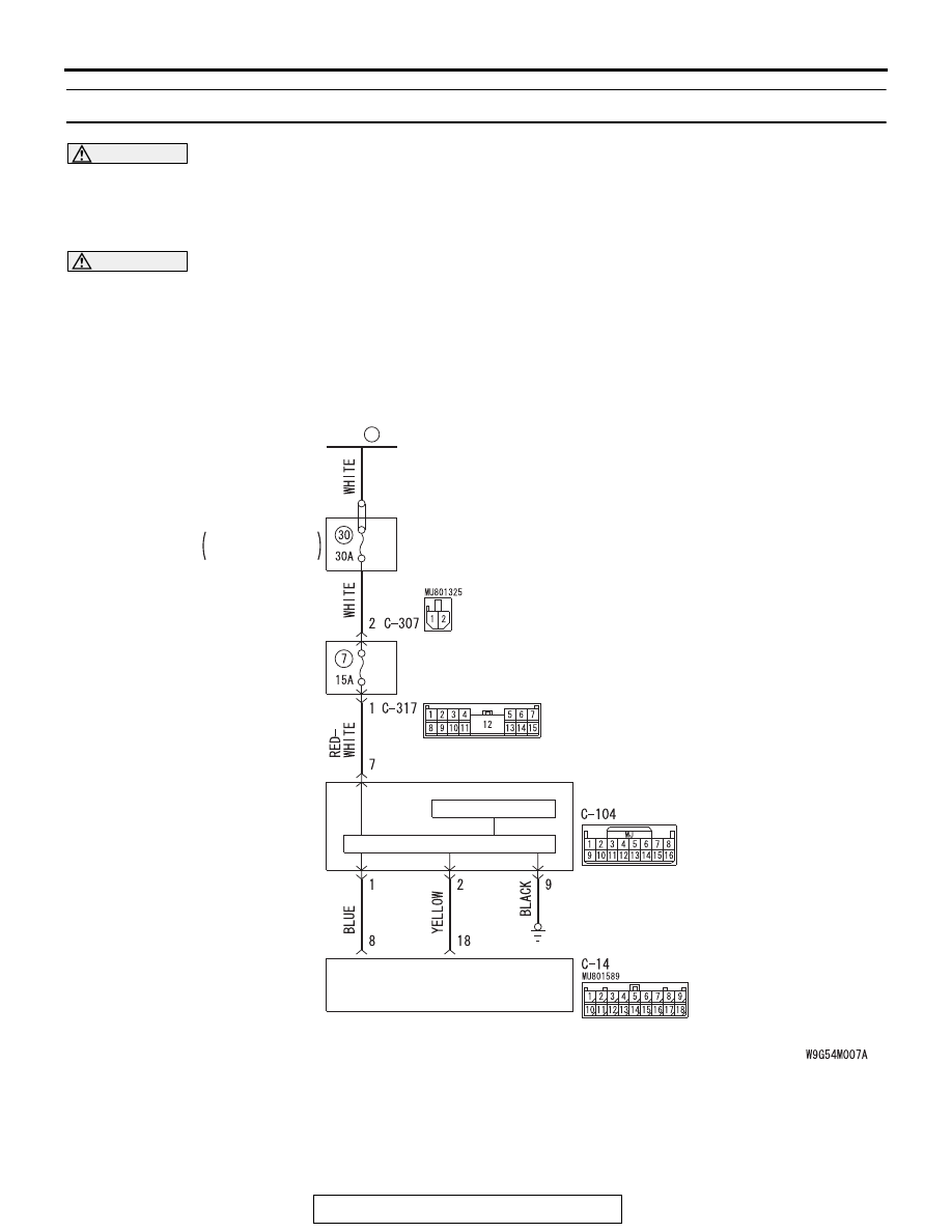
Center Panel Unit Power Supply Circuit

FUSIBLE
LINK

36

CENTER PANEL
UNIT

AUDIO SWITCH PANEL

LCD PANEL

RADIO AND CD PLAYER

ENGINE 
COMPARTMENT

RELAY BOX

RADIO AND CD PLAYER

TSB Revision

CHASSIS ELECTRICAL

54A-358

.

TROUBLE JUDGMENT

If the radio and CD player cannot establish the communication 
with center panel assembly for 1 minute or more, the diagnostic 
trouble code is set.

.

COMMENTS ON TROUBLE SYMPTOM

The radio and CD player, center panel assembly, or CAN bus 
line may have a problem.

.

PROBABLE CAUSES

• Malfunctions of radio and CD player

• Malfunction of center panel assembly

• Malfunction of CAN bus line wiring harness and connector

DIAGNOSIS

Required Special Tools:

• MB991223: Harness Set

• MB992006: Extra Fine Probe

• MB991958: Scan Tool (M.U.T.-III Sub Assembly)

• MB991824: Vehicle Communication Interface (V.C.I.)

• MB991827: M.U.T.-III USB Cable

• MB991910: M.U.T.-III Main Harness A

ACA02655AB

Connector: C-307, C-317

C-307 (B)

C-317

AC703148 BB

Connectors: C-14, C-104

C-14

C-104

RADIO AND CD PLAYER

TSB Revision

CHASSIS ELECTRICAL

54A-359

STEP 1. Using scan tool MB991958, diagnose the CAN bus 
line.
Use scan tool MB991958 to diagnose the CAN bus lines.

CAUTION

To prevent damage to scan tool MB991958, always turn the 
ignition switch to the "LOCK" (OFF) position before con-
necting or disconnecting scan tool MB991958.
(1) Connect scan tool MB991958. Refer to "How to connect the 

Scan Tool (M.U.T.-III) 

P.54A-331

."

(2) Turn the ignition switch to "ON" position.
(3) Diagnose the CAN bus line.
Q: Is the check result normal?

YES : Go to Step 2.
NO :  Repair the CAN bus line. (Refer to GROUP 54C, 

Diagnosis 

P.54C-17

.) On completion, go to Step 2.

STEP 2. Check center panel unit connector C-104 and 
radio and CD player connector C-14 for loose, corroded or 
damaged terminals, or terminals pushed back in the 
connector.
Q: Are center panel unit connector C-104 and radio and CD 

player connector C-14 in good condition?
YES : 
Go to Step 3.
NO :  Repair or replace the damaged component(s) (Refer 

to GROUP 00E, Harness Connector Inspection 

P.00E-2

).

STEP 3. Check the wiring harness between center panel 
unit connector C-104 (terminal 1, 2) and radio and CD 
player connector C-14 (terminal 8, 18).

• Check the communication lines for open circuit and short 

circuit.

Q: Is the wiring harness between center panel unit 

connector C-104 (terminal 1, 2) and radio and CD player 
connector C-14 (terminal 8, 18) in good condition?
YES : 
Go to Step 4.
NO :  The wiring harness may be damaged or the 

connector(s) may have loose, corroded or damaged 
terminals, or terminals pushed back in the connector. 
Repair the wiring harness as necessary.

ZC501967

AC404789

AC702802

MB991824

MB991827

MB991910

Data link

connector

AB

RADIO AND CD PLAYER

TSB Revision

CHASSIS ELECTRICAL

54A-360

STEP 4. Check the ground circuit to the center panel unit. 
Measure the resistance at center panel unit connector 
C-104.
(1) Disconnect the connector, and measure at the wiring 

harness side.

(2) Measure resistance between terminal 9 and ground.

OK: The resistance should be 2 ohm or less.

Q: Is the measured resistance 2 ohms or less?

YES : Go to Step 6.
NO :  Go to Step 5.

STEP 5. Check the wiring harness between center panel 
unit connector C-104 (terminal 9) and ground.

• Check the ground wires for open circuit.

Q: Is the wiring harness between center panel unit 

connector C-104 (terminal 9) and ground in good 
condition?
YES : 
Go to Step 8.
NO :  The wiring harness may be damaged or the 

connector(s) may have loose, corroded or damaged 
terminals, or terminals pushed back in the connector. 
Repair the wiring harness as necessary.

STEP 6. Check the power supply circuit to the center panel 
unit. Measure the voltage at center panel unit connector 
C-104.
(1) Disconnect the connector, and measure at the harness side 

connector.

(2) Measure voltage between terminal 7 and ground.

OK: The voltage should measure approximately 12 
volts (battery positive voltage).

Q: Is the measured voltage approximately 12 volts (battery 

positive voltage)?
YES : 
Go to Step 8.
NO :  Go to Step 7.

AC709322 BM

Harness side: C-104

AC709325 AP

Harness side: C-104


Content   ..  88  89  90  91   ..