Mitsubishi Outlander GS45X. Manual - part 68


  Index      Mitsubishi     Mitsubishi Outlander GS45X - service repair manual


Search            


Content   ..  66  67  68  69   ..


Mitsubishi Outlander GS45X. Manual - part 68


FOG LIGHT

TSB Revision

CHASSIS ELECTRICAL

54A-269

STEP 6. Check the wiring harness between fog light (LH) 
connector A-41or fog light (RH) connector A-51 (terminal 
2) and fog light relay connector A-14X (terminal 3).
NOTE: Also check intermediate connector A-46 for loose, cor-
roded, or damaged terminals, or terminals pushed back in the 
connector. If intermediate connector A-46 is damaged, repair or 
replace the connector as described in GROUP 00E, Harness 
Connector Inspection 

P.00E-2

.

• Check the power supply line for open circuit.

Q: Is the wiring harness between fog light (LH) connector 

A-41 or fog light (RH) connector A-51 (terminal 2) and 
fog light relay connector A-14X (terminal 3) in good 
condition?
YES : 
Go to Step 7.
NO :  Repair the wiring harness.

STEP 7. Retest the system.
Q: Does the right or left fog light illuminate in good 

condition?
YES : 
The trouble can be an intermittent malfunction (Refer 

to GROUP 00, How to use 
Troubleshooting/inspection Service Points 

− How to 

Cope with Intermittent Malfunction 

P.00-15

).

NO :  Go to Step 1.

Inspection Procedure 3: Fog light indicator does not illuminate/go out normally.

CAUTION

Whenever the ECU is replaced, ensure that the 
input and output signal circuits are normal.

.

TECHNICAL DESCRIPTION (COMMENT)

If the fog light indicator does not illuminate normally, connec-
tor(s), wiring harness in the CAN bus lines, the ETACS-ECU or 
the combination meter may be defective.

AC703271

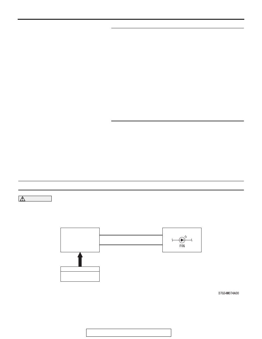
Fog Light Indicator Circuit

INPUT SIGNAL

ETACS-ECU

COMBINATION
METER

CAN COMMUNICATION LINE
(CAN_L LINE)

CAN COMMUNICATION LINE
(CAN_H LINE)

FOG LIGHT SWITCH

AB

FOG LIGHT

TSB Revision

CHASSIS ELECTRICAL

54A-270

.

TROUBLESHOOTING HINTS

• The ETACS-ECU may be defective

• The combination meter may be defective

• Damaged harness wires and connectors

DIAGNOSIS

Required Special Tools:

• MB991223: Harness Set

• MB991958: Scan Tool (M.U.T.-III Sub Assembly)

• MB991824: V.C.I.

• MB991827: M.U.T.-III USB Cable

• MB991910: M.U.T.-III Main Harness A

STEP 1. Check the fog lights.
When the fog light switch is operated, check that the fog lights 
illuminate/go off normally.
Q: Is the fog lights normal?

YES : Go to Step 2.
NO :  First, repair the fog lights. Refer to Inspection 

Procedure 2 "One of the front fog lights does not 
illuminate 

P.54A-266

."

STEP 2. Using scan tool MB991958, diagnose the CAN bus 
line.

CAUTION

To prevent damage to scan tool MB991958, always turn the 
ignition switch to the "LOCK" (OFF) position before con-
necting or disconnecting scan tool MB991958.
(1) Connect scan tool MB991958. Refer to "How to connect the 

scan tool (M.U.T.-III) 

P.54A-257

."

(2) Turn the ignition switch to the "ON" position.
(3) Diagnose the CAN bus line.
(4) Turn the ignition switch to the "LOCK" (OFF) position.
Q: Is the CAN bus line found to be normal?

YES : Go to Step 3.
NO :  Repair the CAN bus line (Refer to GROUP 54C 

− 

Diagnosis 

P.54C-17

).

ZC501967

AC404789

AC702802

MB991824

MB991827

MB991910

Data link

connector

AB

FOG LIGHT

TSB Revision

CHASSIS ELECTRICAL

54A-271

STEP 3. Using scan tool MB991958, read the combination 
meter diagnostic trouble code.
(1) Check whether a combination meter-related DTC is set.
(2) Turn the ignition switch to the "ON" position.

Check whether the combination meter-related DTC is set.

(3) Turn the ignition switch to the "LOCK" (OFF) position.
Q: Is the DTC set?

YES : Diagnose the combination meter (Refer to Diagnosis 

P.54A-34

).

NO :  Go to Step 4.

STEP 4. Using scan tool MB991958, check actuator test.
(1) Turn the ignition switch to the "ON" position.
(2) Perform the actuator test for the combination meter, and 

check that the fog light indicator illuminates (Refer to 

P.54A-91

).

(3) Turn the ignition switch to the "LOCK" (OFF) position.
Q: Is the check result normal?

YES : Replace the ETACS-ECU.
NO :  Replace the combination meter.

ON-VEHICLE SERVICE

FRONT FOG LIGHT AIMING

M1540400300635

PRE-AIMING INSTRUCTIONS

1. Inspect for rusted or faulty front fog light assemblies.
2. These conditions must be corrected before a satisfactory 

adjustment can be made.

3. Inspect tire inflation, and adjust if necessary.
4. If the fuel tank is not full, place a weight in the trunk of the 

vehicle to simulate weight of a full tank [3 kg (6.5 pounds) 
per gallon].

5. There should be no other load in the vehicle other than 

driver or substituted weight of approximately 68 kg (150 
pounds) placed in driver's position.

6. Thoroughly clean the front fog light lenses.
7. Place the vehicle on a level floor, perpendicular to a flat 

screen 7.62 meters (25.0 ft) away from the bulb 
center-marks on the fog light lens.

8. Rock the vehicle sideways to allow the vehicle to assume its 

normal position.

9. Bounce the front suspension through three (3) oscillations 

by applying the body weight to the hood or bumper.

FOG LIGHT

TSB Revision

CHASSIS ELECTRICAL

54A-272

10.Measure the center of the front fog lights as shown in the 

illustration.

11.Four lines of adhesive tape (or equivalent markings) are 

required on screen or wall:

(1) Position a vertical tape or mark so that it is aligned with 

the vehicle center line.

(2) Measure the distance from the center of the front fog light 

lens to the floor. Transfer the measurement to the screen. 
Horizontal tape or mark on the screen is for reference of 
vertical adjustment. 

(3) Measure the distance from the center line of the vehicle 

to the center of each front fog light. Transfer the 
measurement to the screen. Vertical tape or mark on the 
screen is for reference to the center line of each front fog 
light.

FOG LIGHT ADJUSTMENT

1. Check if the beam shining onto the screen is at the standard 

value.

Standard value:

(Cutoff line direction): The horizontal line (H) 153.0 

mm (6.02 inches) (1.15 degrees angle) below the 
horizontal line (H)

Limit:

(Vertical direction): Area from 53.2 mm (2.09 inches) 

(0.4 degrees angle) above the cutoff line to 99.8 
mm (3.93 inches) (0.75 degrees angle) below the 
cutoff line

(Horizontal direction): Vertical line (V) 

± 599.7 mm (± 

23.6 inches) (

± 4.5 degrees angle) 

2. If it is not within the standard value range, adjust by turning 

the adjusting screw.

NOTE: The horizontal direction is non-adjustable. If deviation of 
the light beam axis exceeds the standard value, check that the 
mounting location or some other points are not faulty.

AC900213AC

Fog light center

AC307983AD

(1)

(2)

(3)

Front fog light center

Vehicle center line

(3)

7.62 m (25.0 ft)

Screen

AC407086

Cutoff line

(H)

(V)

Hot zone

mm (in)

53.2 (2.09)

99.8 (3.93)

153.0 

(6.02)

599.7 (23.6) 599.7 (23.6)

AC

AC900215AC

Phillips screwdriver
(Vertical direction
adjustment)


Content   ..  66  67  68  69   ..