Mitsubishi Outlander GS45X. Manual - part 49


  Index      Mitsubishi     Mitsubishi Outlander GS45X - service repair manual


Search            


Content   ..  47  48  49  50   ..


Mitsubishi Outlander GS45X. Manual - part 49


HEADLIGHT

TSB Revision

CHASSIS ELECTRICAL

54A-193

Inspection Procedure 10: The auto light function does not work normally.

CAUTION

Whenever the ECU is replaced, ensure that the 
power supply circuit, the ground circuit and the 
communication circuit are normal.

.

OPERATION

The ETACS-ECU operates this function in accor-
dance with the input signals from driving distance, 
lighting control sensor, and column switch (auto light 
switch). Also, when the column switch (lighting 
switch) is in the "AUTO" position, and when an 
abnormality is present to the auto light circuit, the 
fail-safe function is activated and the low beam is 
turned ON at all times regardless of the brightness 
around the vehicle.

.

TECHNICAL DESCRIPTION (COMMENT)

If the auto light function does not work normally, the 
above input signal circuit(s) or the ETACS-ECU may 
have a problem.

.

TROUBLESHOOTING HINTS

• Malfunction of the lighting control sensor

• Malfunction of the column switch

• Malfunction of the ETACS-ECU

• The wiring harness or connectors may have 

loose, corroded, or damaged terminals, or termi-
nals pushed back in the connector

DIAGNOSIS

Required Special Tools:

• MB991958 Scan Tool (M.U.T.-III Sub Assembly)

• MB991824: Vehicle Communication Interface (V.C.I.)

• MB991827 M.U.T.-III USB Cable

• MB991910 M.U.T.-III Main Harness A (Vehicles with 

CAN communication system)

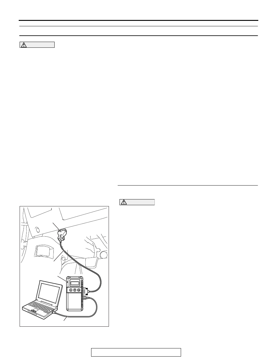
STEP 1. Using scan tool MB991958, diagnose the CAN bus 
line

CAUTION

To prevent damage to scan tool MB991958, always turn the 
ignition switch to the "LOCK" (OFF) position before con-
necting or disconnecting scan tool MB991958.
(1) Connect scan tool MB991958. Refer to "How to connect the 

Scan Tool (M.U.T.-III) 

P.54A-123

."

(2) Turn the ignition switch to the "ON" position.
(3) Diagnose the CAN bus line.
(4) Turn the ignition switch to the "LOCK" (OFF) position.
Q: Is the CAN bus line found to be normal?

YES : Go to Step 2.
NO :  Repair the CAN bus line (Refer to GROUP 54C, 

Diagnosis 

P.54C-17

).

AC608435

Data link connector

MB991827

MB991824

MB991910

AB

HEADLIGHT

TSB Revision

CHASSIS ELECTRICAL

54A-194

STEP 2. Using scan tool MB991958, read the diagnostic 
trouble code.
Check if DTC is set to the LIN.
Q: Is the DTC set?

YES : Refer to DTC chart 

P.54A-127

.

NO :  Go to Step 3.

STEP 3. Using scan tool MB991958, read the ETACS 
diagnostic trouble code.
Check if DTC is set to the ETACS-ECU.
Q: Is the DTC set?

YES : Troubleshoot the ETACS (Refer to 

P.54A-732

).

NO :  Go to Step 4.

STEP 4. Check that the headlights operate.
Check that the headlights (low-beam) illuminate normally.
Q: Is the check result normal?

YES : Go to Step 5.
NO :  Refer to Inspection Procedure 1 "None of headlights 

(low-beam) illuminates." 

P.54A-154

.

STEP 5. Using scan tool MB991958, check data list
Use the ETACS-ECU service data to check the signals related 
to the operation of auto light function.

• Turn the lighting switch to the "AUTO" position.

Q: Does scan tool MB991958 display the items "Headlight 

switch (auto)" as normal condition?
YES : 
Go to Step 6.
NO :  Troubleshoot the ETACS-ECU. Refer to ETACS, 

Diagnosis 

P.54A-785

.

STEP 6. Lighting control sensor check
Check the lighting control sensor. Refer to 

P.54A-220

.

Q: Is the check result normal?

YES : Go to Step 7.
NO :  Replace the lighting control sensor.

STEP 7. Retest the system
Check that the auto light function works normally.
Q: Is the check result normal?

YES : The trouble can be an intermittent malfunction (Refer 

to GROUP 00 

− How to use 

Troubleshooting/inspection Service Points, How to 
Cope with Intermittent Malfunction 

P.00-15

).

NO :  Replace the ETACS-ECU.

Item No.

Item name

Normal 
condition

Item 348

Headlight 
switch (auto)

ON

HEADLIGHT

TSB Revision

CHASSIS ELECTRICAL

54A-195

Inspection Procedure 10: None of turn-signal lights illuminates.

.

TECHNICAL DESCRIPTION (COMMENT)

If none of turn-signal lights illuminates, the ignition 
switch (IG1), the turn-signal light switch input circuit 
or the ETACS-ECU may have a problem.

.

TROUBLESHOOTING HINTS

• Malfunction of column switch

• Malfunction of the ETACS-ECU

• The wiring harness or connectors may have 

loose, corroded, or damaged terminals, or termi-
nals pushed back in the connector

DIAGNOSIS

Required Special Tools:

• MB991958: Scan Tool (M.U.T.-III Sub Assembly)

• MB991824: Vehicle Communication Interface (V.C.I.)

• MB991827: M.U.T.-III USB Cable

• MB991910: M.U.T.-III Main Harness A (Vehicles with 

CAN communication system)

STEP 1. Using scan tool MB991958, read the ETACS-ECU 
diagnostic trouble code.

CAUTION

To prevent damage to scan tool MB991958, always turn the 
ignition switch to the "LOCK" (OFF) position before con-
necting or disconnecting scan tool MB991958.
(1) Connect scan tool MB991958. Refer to "How to connect 

scan tool (M.U.T.-III) 

P.54A-123

."

(2) Turn the ignition switch to the "ON" position.
(3) Check whether the ETACS-ECU DTC is set.
(4) Turn the ignition switch to the "LOCK" (OFF) position.
Q: Is the DTC set?

YES : Diagnose the ETACS-ECU. (Refer to ETACS, 

Diagnosis 

P.54A-732

.)

NO :  Go to Step 2.

ZC501967

AC404789

AC702802

MB991824

MB991827

MB991910

Data link

connector

AB

HEADLIGHT

TSB Revision

CHASSIS ELECTRICAL

54A-196

STEP 2. Using scan tool MB991958, check data list.
Using the ETACS-ECU service data, check the signals related 
to the illumination of turn-signal light.

• Turn the ignition switch to the "ON" position.

Q: Does scan tool MB991958 display the item "IG voltage" 

as normal condition?
YES : 
Go to Step 3.
NO :  Troubleshoot the ETACS-ECU. Refer to Diagnosis - 

Inspection Procedure 2 "ETACS-ECU does not 
receive any signal from the ignition switch (IG1)" 

P.54A-785

.

STEP 3. Retest the system.
Check that turn-signal lights illuminate.
Q: Do turn-signal lights work normally?

YES : The trouble can be an intermittent malfunction (Refer 

to GROUP 00 

− How to use 

Troubleshooting/inspection Service Points 

− How to 

Cope with Intermittent Malfunction 

P.00-15

).

NO :  Replace the ETACS-ECU.

Inspection Procedure 11: The comfort flashing function does not work normally.

.

TECHNICAL DESCRIPTION (COMMENT)

If the comfort flashing function does not work nor-
mally, the turn-signal light switch input circuit(s) and 
ETACS-ECU may have a problem.

.

TROUBLESHOOTING HINTS

• Malfunction of column switch

• Malfunction of the ETACS-ECU

• The wiring harness or connectors may have 

loose, corroded, or damaged terminals, or termi-
nals pushed back in the connector

DIAGNOSIS

Required Special Tools:

• MB991958: Scan Tool (M.U.T.-III Sub Assembly)

• MB991824: Vehicle Communication Interface (V.C.I.)

• MB991827: M.U.T.-III USB Cable

• MB991910: M.U.T.-III Main Harness A (Vehicles with 

CAN communication system)

Item No.

Item name

Normal 
conditions

Item 254

IG voltage

Battery positive 
voltage


Content   ..  47  48  49  50   ..